PWR LEDs, Overload LED
Figure 24: LEDs of the PWRI power supply accessory
The PWR LEDs indicat
e the status of the input voltage on the right and left side of the
PWRI power supply accessory.
The Overload LED indicates an output overload.
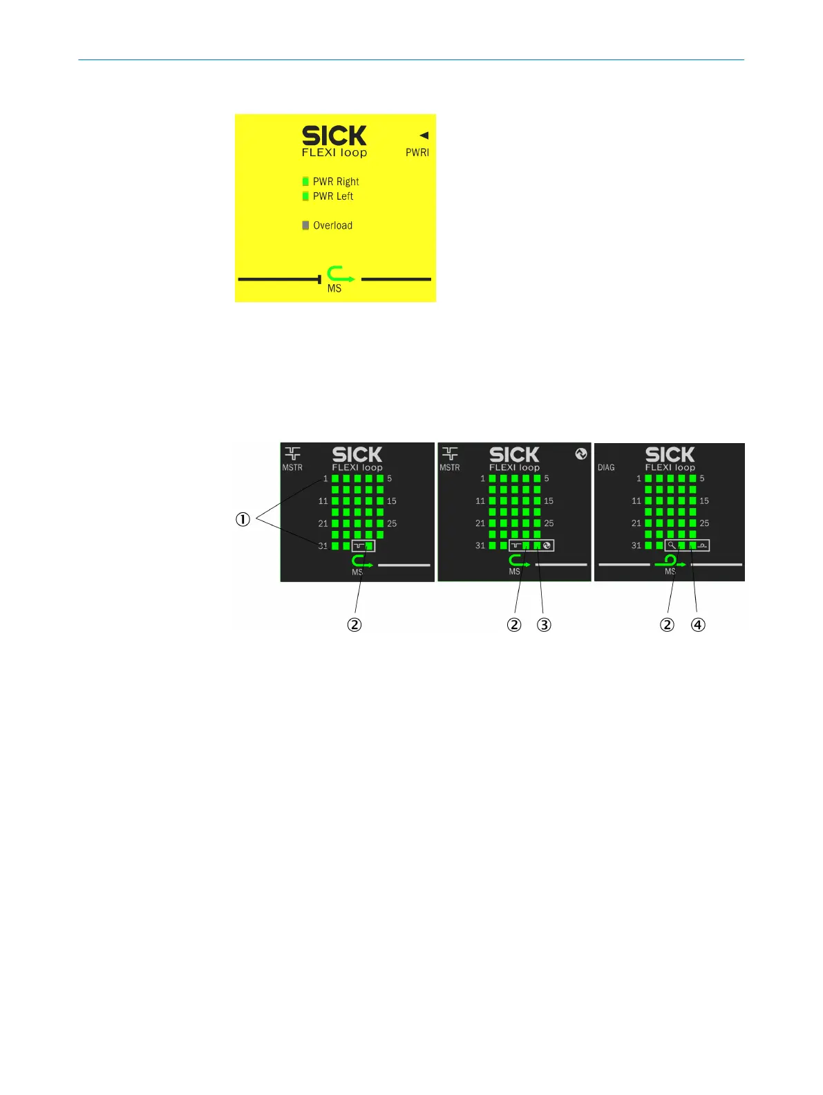
LEDs for the Flexi Loop MSTR2 and DIAG accessories
Figure 25: LEDs for the Flexi Loop MSTR2 and DIAG accessories
1
Node LEDs 1 … 32
2
Operating mode LED
3
IO-Link LED
4
Loop integrity LED
The node LEDs 1 to 32 indicate the status of the Flexi Loop nodes connected.
The oper
ating mode LED indicates the mode in which the Flexi Loop DIAG, MSTR1, or
MSTR2 accessory is currently operating.
The IO-Link LED indicates the status of communication with the IO-Link master.
The loop integrity LED indicates the status of communication in the Flexi Loop safe sen‐
sor cascade.
3 PR
ODUCT DESCRIPTION
26
O P E R A T I N G I N S T R U C T I O N S | Flexi Loop 8015836/YT10/2016-05-24 | SICK
Subject to change without notice