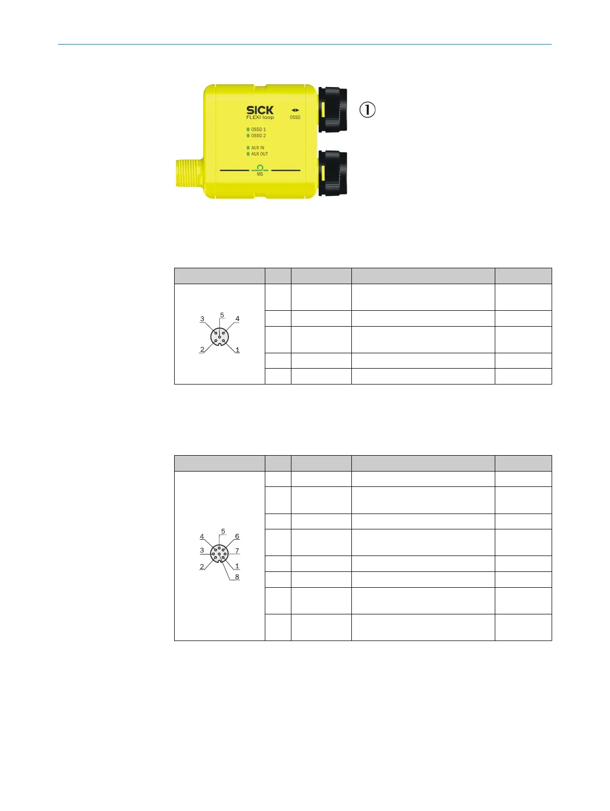
6.2.6 Connections of the OSSD Flexi Loop node
Figure 48: Connections of the OSSD Flexi Loop node
1
OSSD (female connector)
OSSD 5-pin
Female connector Pin Signal Meaning Color
1)
1 VDC 24 V supply voltage for safety
de
vice
Brown
2 OSSD1 Input OSSD1 White
3 GND GND supply voltage
for safety device
Blue
4 OSSD2 Input OSSD2 Black
5 AUX_IN Non-safe input Gray
Table 15: Pin assignment OSSD 5-pin (female connector)
1)
The stated colors apply on the usage of pre-assembled cables (should be checked).
OSSD 8-pin
Female connector Pin Signal Meaning Color
1)
1 AUX_IN Non-safe input White
2 VDC 24 V supply voltage for safety
de
vice
Brown
3 AUX_OUT Non-safe output Green
4 VDC 24 V supply voltage for safety
de
vice
Yellow
5 OSSD1 Input OSSD1 Gray
6 OSSD2 Input OSSD2 Pink
7 GND GND supply voltage for safety
de
vice
Blue
8 VDC 24 V supply voltage for safety
de
vice
Red
Table 16: Pin assignment OSSD 8-pin (female connector)
1)
The stated colors apply on the usage of pre-assembled cables (should be checked).
ELECTRICAL INSTALLATION 6
8015836/YT10/2016-05-24 | SICK O P E R A T I N G I N S T R U C T I O N S | Flexi Loop
47
Subject to change without notice