6.2.5 Connections of the EMSS Flexi Loop node
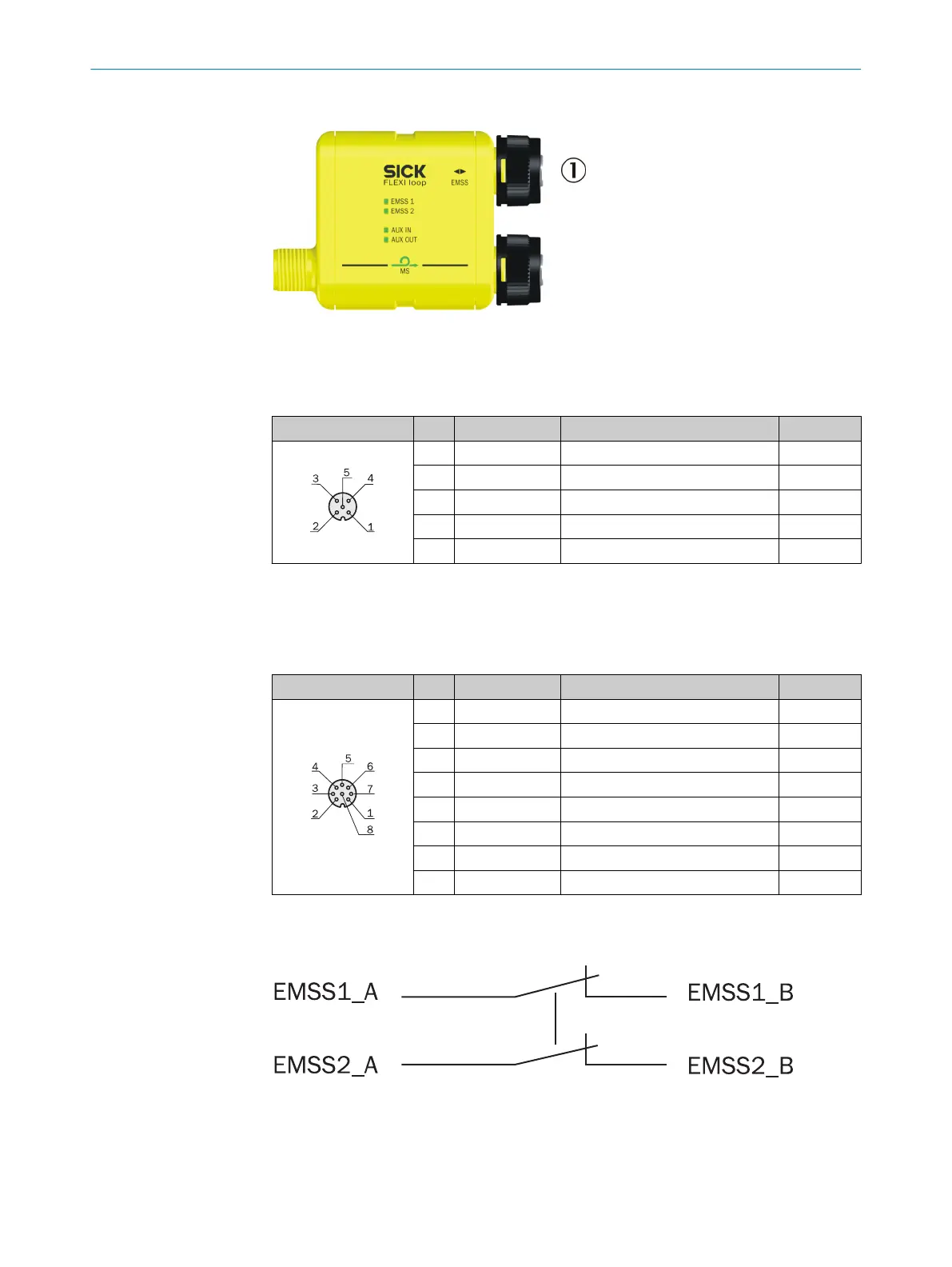
Figure 46: Connections of the EMSS Flexi Loop node
1
EMSS (female connector)
EMSS 5-pin
Female connector Pin Signal Meaning Color
1)
1 EMSS1_A Switching contact 1, connection A Brown
2 EMSS1_B Switching contact 1, connection B White
3 EMSS2_A Switching contact 2, connection A Blue
4 EMSS2_B Switching contact 2, connection B Black
5 EMSS2_A Switching contact 2, connection A Gray
Table 13: Pin assignment EMSS 5-pin (female connector)
1)
The stated colors apply on the usage of pre-assembled cables (should be checked).
EMSS 8-pin
Female connector Pin Signal Meaning Color
1)
1 VDC 24 V supply voltage White
2 AUX_IN Non-safe input Brown
3 EMSS1_A Switching contact 1, connection A Green
4 EMSS1_B Switching contact 1, connection B Yellow
5 AUX_OUT Non-safe output Gray
6 GND GND supply voltage Pink
7 EMSS2_A Switching contact 2, connection A Blue
8 EMSS2_B Switching contact 2, connection B Red
Table 14: Pin assignment EMSS 8-pin (female connector)
1)
The stated colors apply on the usage of pre-assembled cables (should be checked).
Figure 47: Connection sketch dual-channel equivalent switch
An e
xample application for the connection of a lock: see "Implementation of a safety
locking device", page 36.
6 ELECTRIC
AL INSTALLATION
46
O P E R A T I N G I N S T R U C T I O N S | Flexi Loop 8015836/YT10/2016-05-24 | SICK
Subject to change without notice