DANGER
Alw
ays supply the OSSD devices connected with power via the OSSD female connector
on the FLN-OSSD1000105 or FLN-OSSD1100108 Flexi Loop node!
Never supply an OSSD device connected with power directly from a separate power sup‐
ply. If several power supplies are connected in parallel, in case of a ground fault over‐
current and a cable fire may occur.
The OSSD devices must be connected to the same voltage supply as the Flexi Loop
nodes to which the OSSDs are connected.
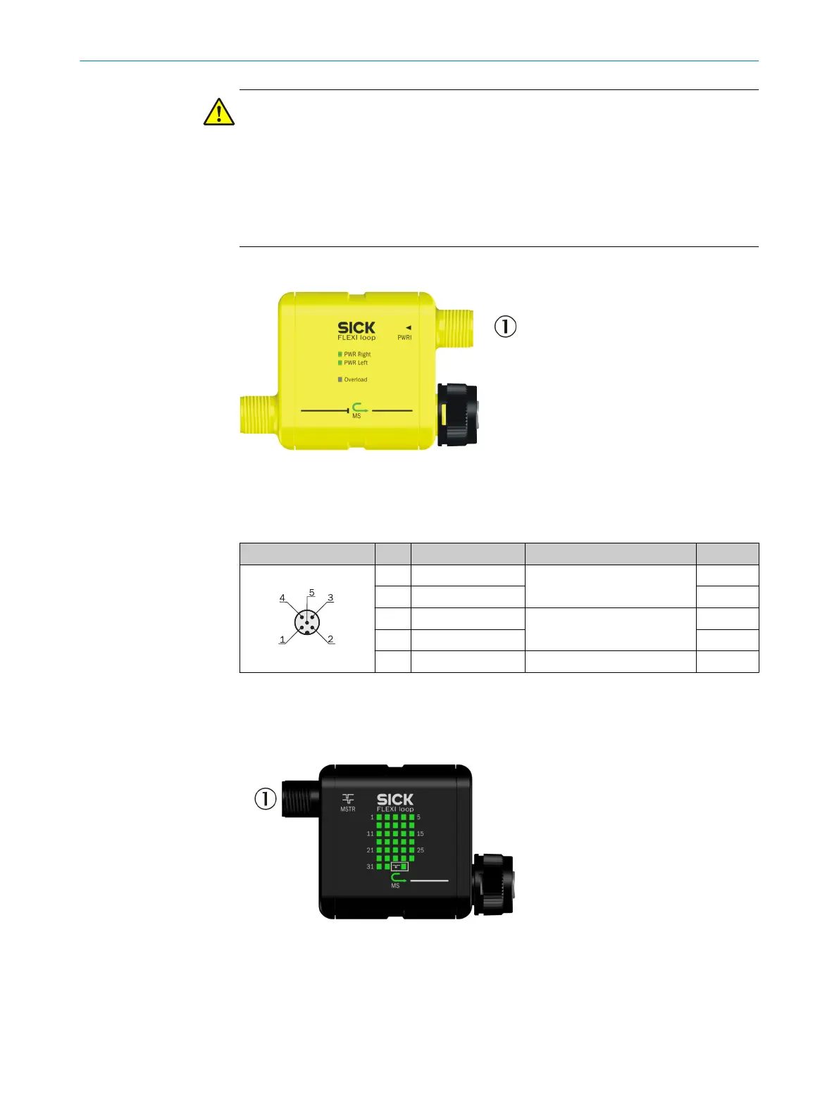
6.2.7 Connections of the PWRI power supply accessory
Figure 49: Connections of the PWRI power supply accessory
1
PWRI (male connector)
PWRI 5-pin
Male connector Pin Signal Meaning Color
1)
1 VDC 24 V supply voltage
of t
he power supply connected
Brown
2 VDC White
3 GND GND from the power supply
connect
ed
Blue
4 GND Black
5 Do not use Gray
Table 17: Pin assignment PWRI 5-pin (male connector)
1)
The stated colors apply on the usage of pre-assembled cables (should be checked).
6.2.8 Connections of the MSTR1 Flexi Loop accessory
Figure 50: Connections of the MSTR1 Flexi Loop accessory
1
FC_IN (male connector)
6 ELECTRICAL INSTALLATION
48
O P E R A T I N G I N S T R U C T I O N S | Flexi Loop 8015836/YT10/2016-05-24 | SICK
Subject to change without notice