The problem of error masking
If t
ested dual-channel equivalent safety switches are connected in series, errors cannot
be detected reliably. The following example shows such a situation.
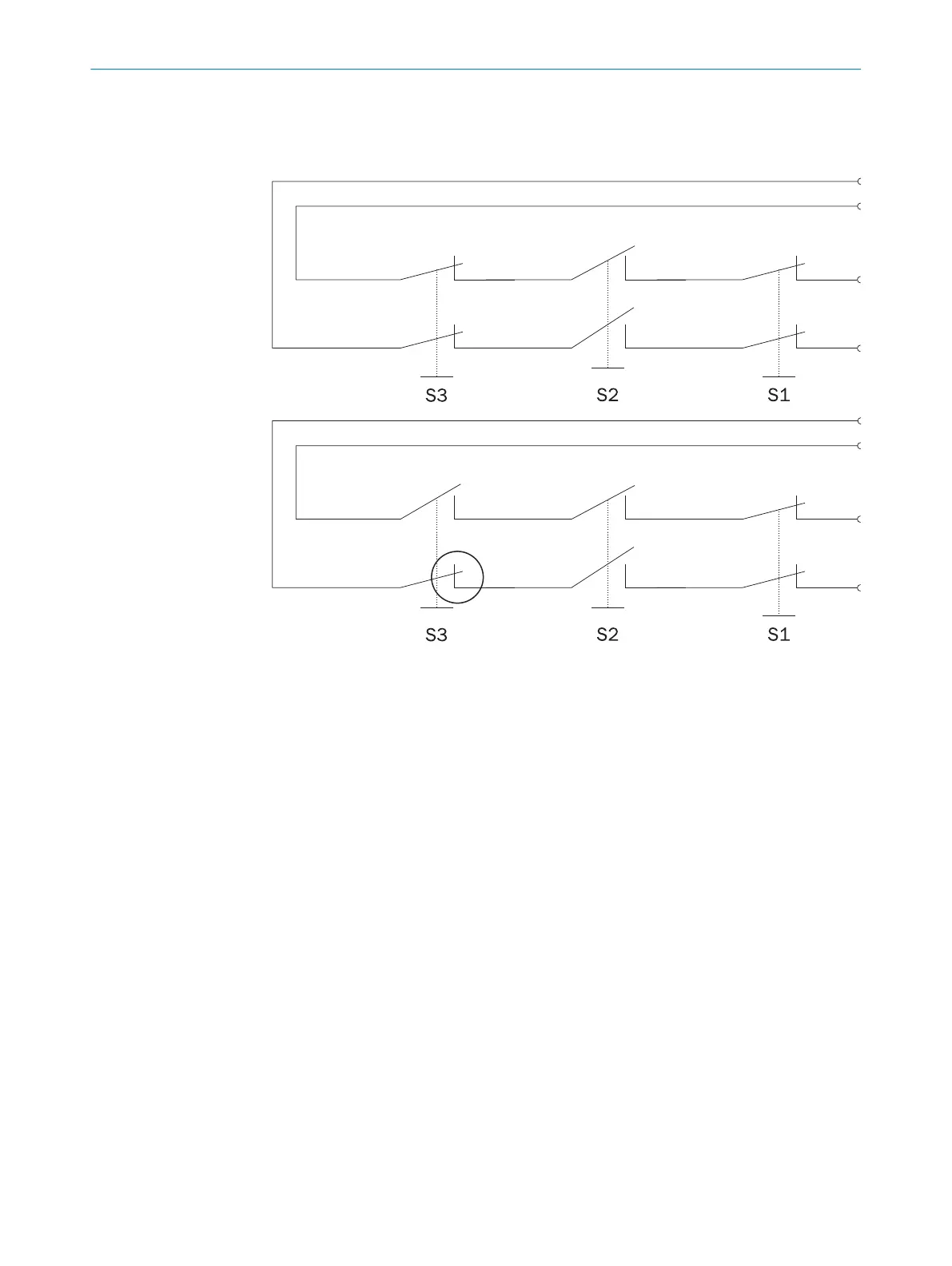
Figure 2: Error masking
If t
he switch S2 is opened correctly, e.g. the system is shut down. If the switch S3 is
now also opened, the error on S3 cannot be detected (error masking). If the switch S3
is closed before S2, the error remains undetected.
3.1.3 Subdivision of the safe sensor cascade
The safe sensor cascade is divided into segment, section and string:
•
Segment
A segment s
tarts at the safety controller or the FL_OUT female connector of the
upstream Flexi Loop node; it includes the connection cable as far as the FL_OUT
female connector of the Flexi Loop node (see "Connections of the Flexi Loop
nodes", page 44) and the supply lines to the devices that are connected to the
Flexi Loop node.
•
section
A section extends from a supply of power to the next accessory for the supply of
power or to the terminator.
•
string
A string covers the complete safe sensor cascade from the connection on the
safety controller to the terminator.
PRODUCT DESCRIPTION 3
8015836/YT10/2016-05-24 | SICK O P E R A T I N G I N S T R U C T I O N S | Flexi Loop
13
Subject to change without notice