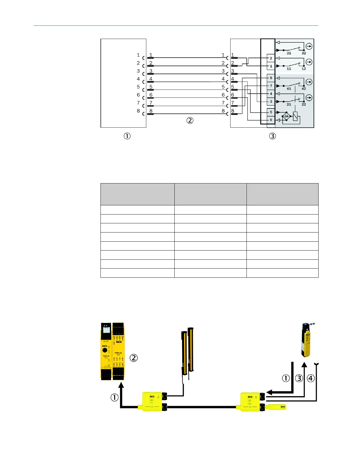
Figure 33: Connection of a safety locking device to the EMSS node
1
EMSS node
2
Connecting cable M12, 8-pin, male/female connector
3
Safety locking device i10 Lock, i10-M0454
Pin assignment
8-pin EMSS
(female connector)
Signal Pin assignment
i10 lock, i10-M0454
(male connector)
1 VDC 1
2 AUX_IN 2
3 EMSS1_A 3
4 EMSS1_B 4
5 AUX_OUT 5
6 GND 6
7 EMSS2_A 7
8 EMSS2_B 8
Table 11: Pin assignment safety locking device to EMSS node
Implementation with the Flexi Soft safety controller
The loc
k must be implemented in the Flexi Soft Designer logic editor (see the “Flexi
Loop in the Flexi Soft Designer” operating instructions, part no. 8014522).
Figure 34: Lock with the Flexi Soft safety controller
1
Safe cut-off path (guard position monitoring of the protective device and the interlocking
de
vice)
DESIGN 4
8015836/YT10/2016-05-24 | SICK O P E R A T I N G I N S T R U C T I O N S | Flexi Loop
37
Subject to change without notice