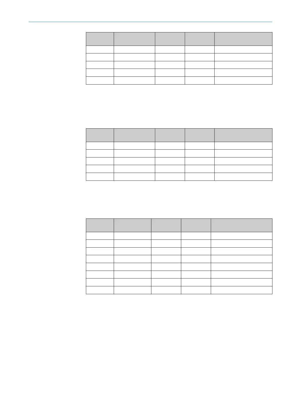
Segment Wire cross-section
[mm²]
Cable length
[m]
Voltage VDC
[V]
Current consumption of
connect
ed devices [A]
1 0.75 15.00 23.38 0.00
2 0.75 15.00 22.80 0.00
…
14 0.75 15.00 18.96 0.00
15 0.75 15.00 18.89 0.00
Table 7: Example voltage drop on 15 Flexi Loop nodes with wire cross-section 0.75 mm²
Devices with current consumption
If de
vices with a current consumption are connected to the Flexi Loop node (in the
example with 0.5 A and with 1.5 A), the input voltage drops below the permissible value
from the 2
nd
Flexi Loop node.
Segment Wire cross-section
[mm²]
Cable length
[m]
Voltage VDC
[V]
Current consumption of
connected devices [A]
1 0.34 15.00 20.00 0.50
2 0.34 15.00 16.86 1.50
3 0.34 15.00 16.14 0.00
…
10 0.34 15.00 13.42 0.00
Table 8: Example voltage drop due to current consumption of connected devices
Solution example with PWRI power supply accessory
By using a PWRI power supply accessory after the 5
th
Flexi Loop node, the input voltage
is adequate at all 10 Flexi Loop nodes.
Segment Wire cross-sec‐
tion [mm²]
Cable length
[m]
Voltage VDC
[V]
Current consumption of con‐
nect
ed devices [A]
1 0.34 15.00 23.02 0.50
2 0.34 15.00 22.12 1.50
…
5 0.34 15.00 17.07 0.00
FLA-PWRI
1 0.34 15.00 23.97 0.00
…
5 0.34 15.00 22.93 0.00
Table 9: Example voltage drop on 10 Flexi Loop nodes with PWRI
Solution example with increased wire cross-section
Using a wir
e cross-section of 0.75 mm² will ensure that a sufficient input voltage is
available even at the 10th Flexi Loop node.
DESIGN 4
8015836/YT10/2016-05-24 | SICK O P E R A T I N G I N S T R U C T I O N S | Flexi Loop
33
Subject to change without notice