Segment Wire cross-section
[mm²]
Cable length
[m]
Voltage VDC
[V]
Current consumption of
connect
ed devices [A]
1 0.34 15.00 23.10 0.00
2 0.34 15.00 22.29 0.00
…
9 0.34 15.00 18.98 0.00
10 0.34 15.00 18.85 0.00
Table 4: Example voltage drop on 10 Flexi Loop nodes
However, if 15 Flexi Loop nodes are used in the same conditions, the input voltage
dr
ops below the permissible value from the 7
th
Flexi Loop node.
Segment Wire cross-section
[mm²]
Cable length
[m]
Voltage VDC
[V]
Current consumption of
connected devices [A]
1 0.34 15.00 22.68 0.00
2 0.34 15.00 21.44 0.00
…
6 0.34 15.00 17.33 0.00
7 0.34 15.00 16.52 0.00
…
15 0.34 15.00 13.08 0.00
Table 5: Example voltage drop on 15 Flexi Loop nodes
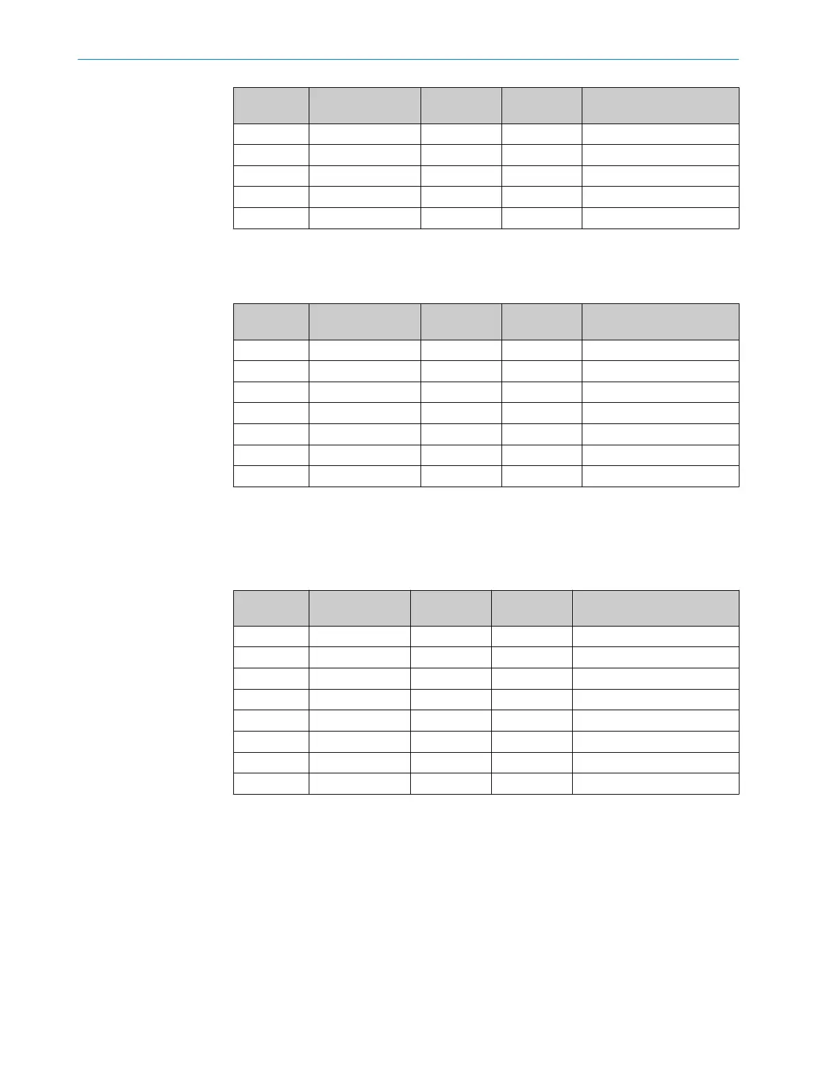
Solution example with PWRI power supply accessory
By using a PWRI po
wer supply accessory after the 11
th
Flexi Loop node, the input volt‐
age is adequate at all Flexi Loop nodes.
Segment Wire cross-sec‐
tion [mm²]
Cable length
[m]
Voltage VDC
[V]
Current consumption of con‐
nect
ed devices [A]
1 0.34 15.00 23.02 0.00
2 0.34 15.00 22.12 0.00
…
11 0.34 15.00 17.86 0.00
FLA-PWRI
1 0.34 15.00 23.02 0.00
…
4 0.34 15.00 20.58 0.00
Table 6: Example voltage drop on 15 Flexi Loop nodes with PWRI
Solution example with increased wire cross-section
Using a wir
e cross-section of 0.75 mm² will ensure that a sufficient input voltage is
available even at the 15th Flexi Loop node.
4 DESIGN
32
O P E R A T I N G I N S T R U C T I O N S | Flexi Loop 8015836/YT10/2016-05-24 | SICK
Subject to change without notice