11
8009441/YN36/V3-0/2015-08| SICK OPERATING INSTRUCTIONS|GM35
Subject to change without notice
PRODUCT OVERVIEW
– Output of measured values, computed data and operating states
– Communication with the peripheral equipment
– Output of error messages and other status signals
– Control of automatic test functions and access during service (diagnosis)
• Connection cables
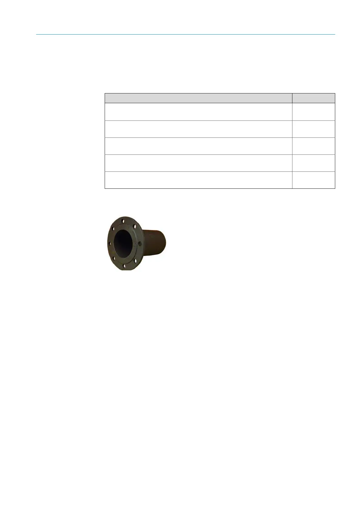
• Flanges with tube
To install the SR-unit and reflector on the gas duct. The purge
air fixtures onto which the SR-unit and reflector are later
mounted are secured to the flanges. Dimension drawing and
order data,
see page 118. ANSI or DIN flanges provided by the
customer can be used alternatively to the flanges supplied.
Cable type Part No.
Cable
*)
(CAN bus), SR-unit – purge air fixture, length 0.8 m
Connection cable
[1]
, 5, 10, 12, 15 or 24 m available as accessory.
2023704
Cable
[2]
(CAN bus), SR-unit – evaluation unit, length 4 m
Scope of
delivery
Cable
*)
, purge air fixture SR-unit – filter monitor for purge air unit, length
5 m;
2032143
2 cables
*)
, purge air fixture SR-unit – filter monitor for purge air unit,
length 2 m as extension;
6025923
Cable, purge air fixture SR-unit – filter monitor for purge air unit, length
3 m as extension
6028663
[1] One length included in scope of delivery
[2] Included in scope of delivery

 Loading...


