14
8009441/YN36/V3-0/2015-08| SICKOPERATING INSTRUCTIONS|GM35
Subject to change without notice
PRODUCT OVERVIEW
2.3 Functional principle
2.3.1 Opto-electronic in-situ measuring principle
The Gas Analyzer GM35 is based on the in-situ technique using opto-electronic direct
measurement. Measured values are recorded through no-contact measurement directly in
the gas flow across the entire duct cross-section (cross-duct). The GM35 SR-unit
determines the concentration of the respective gas component based on wavelength-
specific light absorption by the gas mixture in the active measuring path.
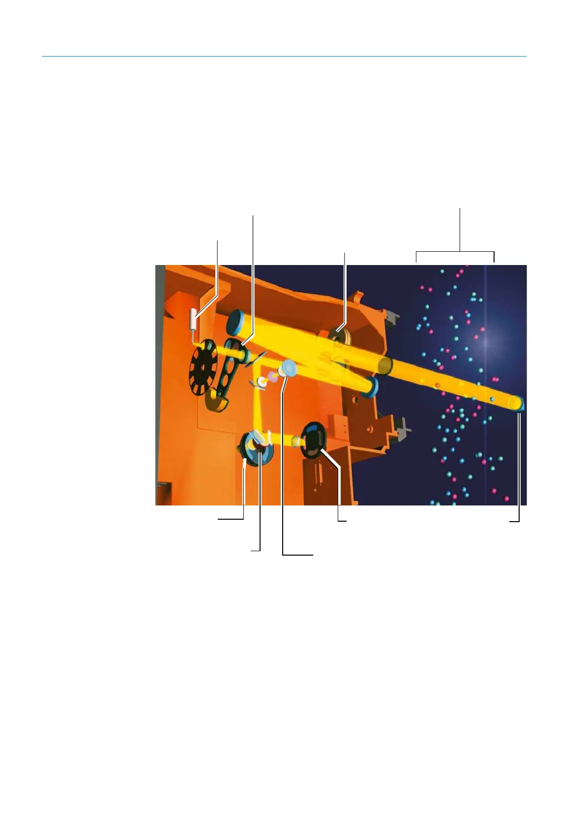
Fig. 3: Optics layout for the GM35
The beam from the sender/receiver unit (SR-unit) passes lengthwise through the active
measuring path (see
see “Fitting recommendation for the mounting flange (duct diameter
not representative)”, page 20) and is reflected by the reflector at the other end. The
reflected light from the beam splitter then passes through a filter or cell wheel to detectors
configured optionally to measure CO, N
2
O as well as CO
2
and H
2
O. By filtering the light
received into its spectral components, the receiver elements record the absorption of the
gas molecules at characteristic points of the spectrum in the IR range of 1.6 to 4.9 µm.
Cross-sensitivities with gases other than those to be measured are avoided by selecting
these evaluation ranges within the IR spectrum in conjunction with the evaluation algo-
rithms used (see
“Signal evaluation”, page 15).
CO or
N
2
O detector
Measuring path in gas duct
Cell wheel and detector
for CO- or N
2
O measurement
IR transmitter
lamp
Zero point reflector
and blanking diaphragm
Filter Fwheel and detector
for CO
2
and H
2
O
Reflector
Reference filter for pivoted
segment
Visor with opto-electronic adjustment tool
Filter wheel and detector
or CO
2
and H
2
O

 Loading...


