114
8009441/YN36/V3-0/2015-08| SICKOPERATING INSTRUCTIONS|GM35
Subject to change without notice
TECHNICAL DATA, CONSUMABLES AND SPARE PARTS
10.1.1 GM35 system component
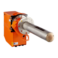
GM35 Sender/receiver unit
Measuring principle In-situ, IR filter or gas correlation
Light source IR source
Detectors PbS and PbSe
Response time (t
90
) ≥ 5s
Averaging Can be parameterized as floating integral over 5 to 300 seconds
Interfaces CAN bus (electrically isolated) for transferring data within the GM35
measuring system
RS232 (Service interface)
Indicators • Status LED (operation: green, maintenance: yellow, malfunction/
failure: red)
• Displays the optical alignment
Protection class IP 65 / NEMA 4x
Sample gas tempera-
ture
• 430 °C max.
• N
2
O: 180 °C max.
Ambient temperature • –20 to +55 °C; other temperatures on request
(tested for suitability according to minimum requirement
–20 … 50 °C)–40 °C during continuous operation
Temperature change Max. 10 °C/h
Ambient humidity Max. 96 % rF
Humidity condensation Humidity condensation on optical interfaces not allowed
Shock and vibration As defined in EN 61010-1
Storage temperature –30 to +55 °C
Power supply 115/230 V AC ±10%, 48–62 Hz
Power input 350 VA max.
Dimensions (WxHxD) 291 x 530 x 570 mm
Weight 29 kg
Table 6:
GM35 Reflector unit
Reflector material Gold-coated hollow triple
Protection class IP 65 / NEMA 4x
Dimensions (L x
∅) 140 x 133 mm
Weight 1.5 kg
GM35 Purge air fixtures
Integrated sensors • Flow monitor to monitor purge air feed
• Temperature sensor (purge air)
• Pressure sensor
Data transfer CAN bus (electrically isolated)
Dimensions (L x ∅) 220 x 240 mm
Weight 7 kg

 Loading...