124
8009441/YN36/V3-0/2015-08| SICKOPERATING INSTRUCTIONS|GM35
Subject to change without notice
TECHNICAL DATA, CONSUMABLES AND SPARE PARTS
Table 10: Spare parts purge air fixture, SR-unit
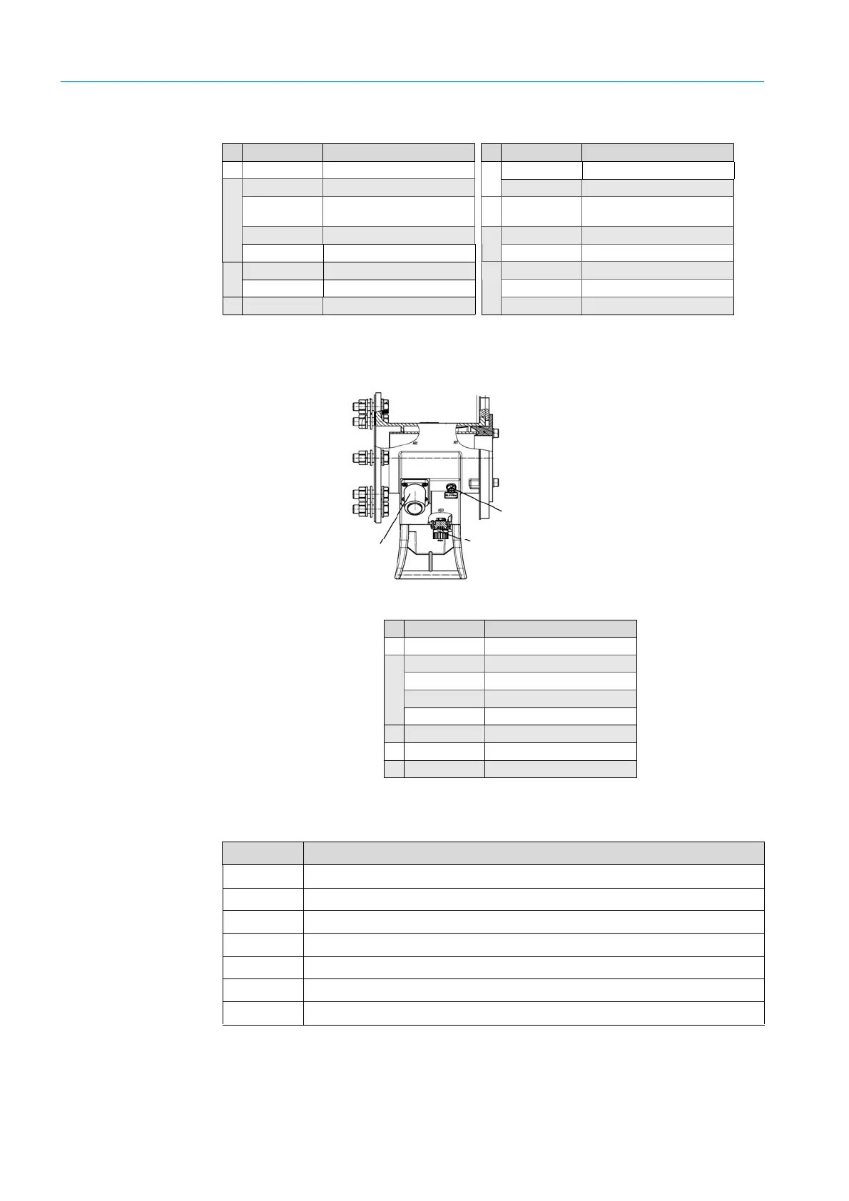
10.3.5 Spare parts for purge air fixture - reflector side
Fig. 89: Position of spare parts for the purge air fixture, reflector side
Table 11: Spare parts for purge air fixture, reflector
10.3.6 Spare parts for the evaluation unit
Part No. Spare part Part No. Spare part
2031895 Electronic board
2 031 202 Plug, PT 1000
2031228
Purge air nozzle,
90
m
3
2 020 432 CAN connector (female)
5308390 O-ring, 42 x 2
6 007 489 Protection cap
5 04299 O-ring, 8 x 2
5 309 133 Swagelok union
5303806 Screw, M5 x 12
5 309 134
1
/
4
” plug
2020020 CAN connector (male)
5 312 915 Hose, 6.4/4.3 mm
6007488 Protection cap
5 311 127 Gasket, 12/15.5 x 1.5
2032031 Plug, purge air unit 5 309 138 Hose inlet support
Part No. Spare part
2031895 Electronic board
2031228
Purge air nozzle,
90
m
3
5308390 O-ring, 42 x 2
5 04299 O-ring, 8 x 2
5303806 Screw, M5 x 12
2032031 Plug, purge air unit
2020020 CAN connector (male)
6007488 Protection cap
Part No. Name
2 021 795 PCB system control
6 021 782 Fuse 250 V, D8.5 x 8
6 020 125 Locking cap, fuse D5 x 20
6 007 328 Jumper, pluggable
6 020 400 Membrane keyboard
2 017 329 Hinge pin
6 010 378 Lithium battery 3.00 V CR2032

 Loading...


