73
8009441/YN36/V3-0/2015-08| SICK OPERATING INSTRUCTIONS|GM35
Subject to change without notice
START-UP
Note Flange dimensions, see “Flange with tube dimensions”, page 118
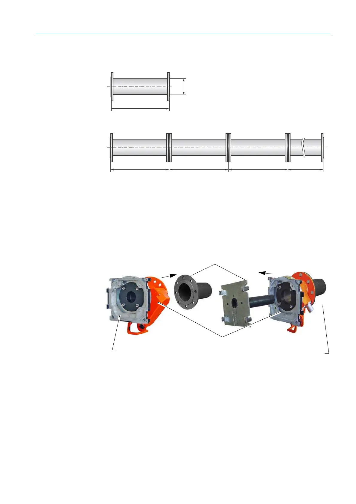
Fig. 52: Zero path
7.4.2 Installing the GM35 system components
1. Fitting the purge air fixtures:
Fit the purge air fixtures on the flange with tube or zero path
SR-unit:
▸ Use the 4 M16 screws to fit the purge air fixture with device flange to the flange with
tube.
Reflector side:
▸ Use the 4 M16 screws to fit the purge air fixture with reflector on the flange with tube.
Fig. 53: Fitting the purge air fixtures on the flange with tube
2. Installing the adjustment device:
SR-unit:
▸ Position the light source of the adjustment device in the device flange and secure
using the quick-release fasteners.
≤ 2 m
2 m 2 m 2 m ≤1.5 m
Flange - flange distance up to 2 m
Flange - flange distance up to max. 7.5 m
∅ ≥0.2m
Device flange
Purge air fixtures
Flanges
Reflector head

 Loading...


