74
8009441/YN36/V3-0/2015-08| SICKOPERATING INSTRUCTIONS|GM35
Subject to change without notice
START-UP
Reflector side:
▸ Remove the reflector head from the reflector flange; keep the Allen screws for the
head in a safe place because you will need them later when reinstalling the head.
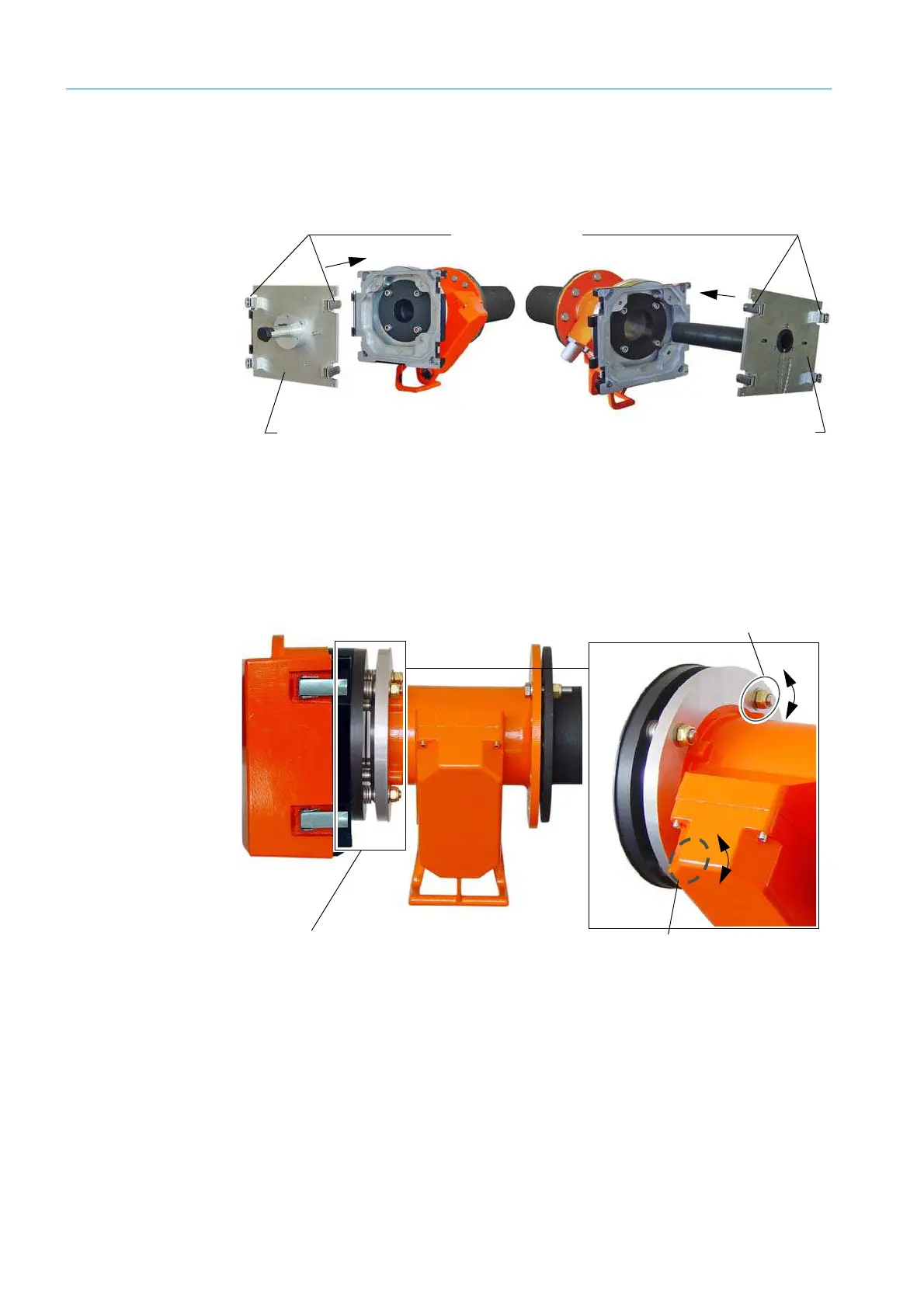
▸ Insert the adjustment device telescope and secure with the screws.
Fig. 54: Securing the adjustment device
3. Aligning the purge air fixtures:
Reflector side:
▸ Adjust the two screws of the L adjustment until the light spot in the telescope of the
alignment tool appears in the center of the target (
see “Optical alignment – shown on
telescope”, page 75
, left).
Fig. 55: L adjustment to align the flange - purge air fixture (example: reflector flange)
Alignment tool –
light source
Adjustment device
telescope
Quick-release fasteners
Horizontal adjustment
Vertical adjustment
(screw hidden)
Adjustment screws
Fixing (shown here without sealing
tape)

 Loading...


