81
8009441/YN36/V3-0/2015-08| SICK OPERATING INSTRUCTIONS|GM35
Subject to change without notice
START-UP
7.6 Starting measuring operation
This Section describes the final preparations at the measuring point at which the
Gas Analyzer GM35 starts measuring operation. The SR-unit and reflector with fitted purge
air fixture must already be installed at the measuring point.
7.6.1 Installing the purge air fixtures
Fit the purge air fixtures on the flange with tube or zero path
SR-unit:
▸ Use the 4 M16 screws to fit the purge air fixture with device flange to the flange with
tube.
Reflector side:
▸ Use the 4 M16 screws to fit the purge air fixture with reflector on the flange with tube.
▸ Align the purge air fixture using the adjustment device as described in
“Installing the
GM35 system components”, page 73.
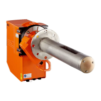
Fig. 61: Fitting the purge air fixtures on the flange with tube
Note Position the SR-unit and reflector in the immediate vicinity of the sample gas duct so that
the purge air hoses can be connected and the measuring system fitted while the purge air
units are running.
7.6.2 Purge air units start-up
Installation and electrical connections for purge air units have already been described dur-
ing installation,
see “Preparations for electrical installation”, page 25 to “CAN bus wiring
options”, page 36.
▸ Switch the power supply for each of the purge air units on for a short time to check the
function and to remove any dust that may have penetrated the purge air hose.
On each of the SR and
reflector sides
▸ Connect each of the purge air hoses (from the purge air unit) to the purge air connection
of the fitting with a hose clamp.
▸ Switch the purge air supply on.
CAUTION: Follow the work sequence
To prevent damage to health and the measuring system, carry out the steps
described in the following in the specified sequence. Always observe the
relevant safety information.
Device flange
Purge air fixtures
Flanges with tube
Reflector flange
Reflector head

 Loading...