91
8009441/YN36/V3-0/2015-08| SICK OPERATING INSTRUCTIONS|GM35
Subject to change without notice
MAINTENANCE
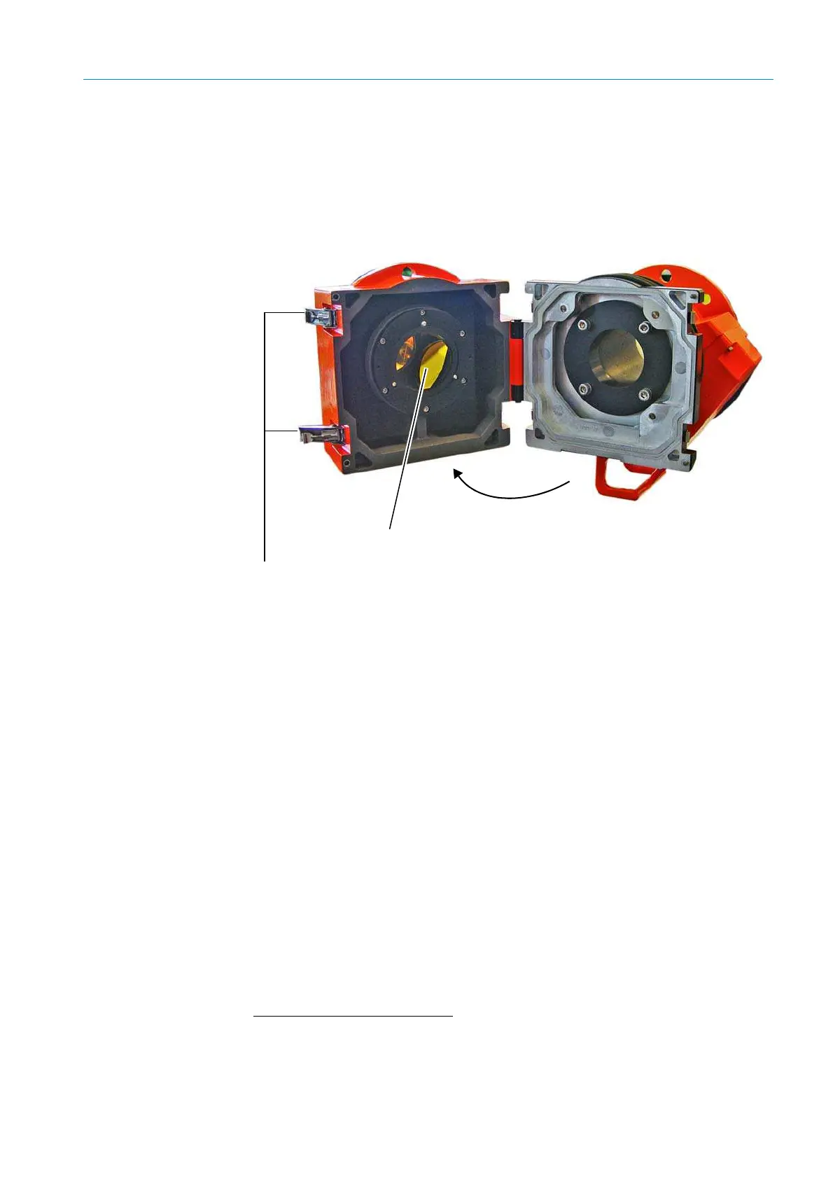
8.3.3 Cleaning the optical interface (window) on the reflector
▸ Open the quick-release fasteners on the reflector head and open the reflector
▸ Check the optical interface (window) on the reflector for contamination and, if
necessary, clean using an optical cleaning cloth. Do not use any detergents because
these leave invisible residues that could falsify the measuring result. The cleaning cloths
can be moistened with distilled water if necessary.
▸ Swivel the reflector head in again and close the quick-release fasteners.
>
Fig. 68: Optical interface (window) on the reflector
▸ Check the zero point setting,
see “Performing zero adjust”, page 80.
8.3.4 Checking the zero point
The zero point of the GM35 can also be checked on a measuring path or zero path free
from sample gas. This can be carried out directly in the duct when it is ensured that no
more sample gas is present in the duct, e.g. the plant has been shut down. In this case,
observe the measured values on the EvU display and carry out zero adjust, see below.
Note Zero path, “Measuring path free from sample gas - zero path”, page 72.
▸ Put the GM35 components (SR-unit with purge air fixture
[1]
, reflector with purge air
fixture, possibly an EvU) out of operation (disconnect the power supply) and remove.
▸ Install the GM35 components on the measuring path free from sample gas and make all
connections,
see “Installing the GM35 system components”, page 73.
▸ Observe the measured values on the EvU display and carry out zero adjust,
see “Per-
forming zero adjust”, page 80
.
▸ Once zero adjust has completed successfully, install the GM35 components (SR-unit
with purge air fixture, reflector with purge air fixture, EvU) at the measuring location and
start measuring operation again, see “Starting measuring operation”, page 81.
Optical interface (front window)
Quick-release fasteners
[1] Depending on the existing zero path

 Loading...


