18
8009441/YN36/V3-0/2015-08| SICKOPERATING INSTRUCTIONS|GM35
Subject to change without notice
PROJECT PLANNING INFORMATION
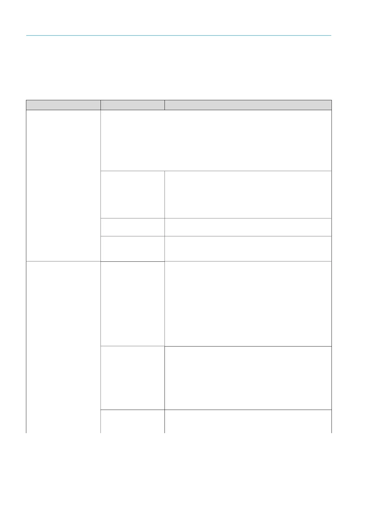
3.2 Project Planning Checklist
Project planning, step by step
Technical data and dimensional drawings of system components,
see “Technical Data,
Consumables and Spare Parts”, page 113 and following.
Topic Task Measure/determination
Determining the
measuring point
Observe national
regulations such as
VDI 3950.
Provide for unhindered inlet and outlet paths:
▸ For round duct cross-sections: 3 times the duct diameter
▸ For rectangular cross-sections: Hydraulic diameter
▸ If these specifications cannot be met: Inlet path > outlet path,
e.g.
2
/
3
:
1
/
3
; uniform concentration spread whenever possible
Emission measuring
point
▸ Obtain official approval for emission measuring point.
▸ Provide for calibration openings at easily accessible places.
▸ Ensure the GM35 and calibration probe do not influence
each other; the calibration gland should be located at a
minimum distance of 0.5 m upstream of the measuring
device.
Application conditions
▸ Observe Technical Data for duct/ambient conditions!
▸ Gas temperature above/below dew point (dry/wet)
Pressure conditions at
the measuring point
▸ A fitting location with partial vacuum in the duct is ideal.
▸ For duct pressures > 10 hPa/mbar, please contact SICK to
select the correct purge air blower type.
SR-unit, reflector
see “Assembly prepara-
tion at the measuring
point”, page 20
.
Select suitable flange
with tube
● The flange is designed to be installed in steel ducts; suitable
flanges with tube are usually supplied with the GM35.
● Stone stacks or ducts with thick walls demand an onsite
retaining plate and, possibly, a longer version of the flange
with tube;
see “Installing the flanges with tube”, page 21.
● If some of the components have not yet been delivered, you
may need to arrange an advance delivery of the flanges with
tube so that you can mount these as part of the
preparations for installation onsite.Alternatively, you can use
a suitable flange prepared onsite (or ANSI flange, check the
Technical Data, see
see “Technical Data, Consumables and
Spare Parts”, page 113
).
Select stack opening
▸ Provide an opening of suitable size for the flange tube.
▸ Provide for adequate clearance for installation and
maintenance activities for the duct insulation cutout.
▸ Plan clearances for handling the SR-unit, reflector.
▸ Ensure the ambient temperature for the SR-unit and
reflector is between –20 and +55 °C (–40 °C during
continuous operation).
▸ For installation outdoors, plan a weatherproof cover
Tools for start-up and
maintenance
● When working on the zero path; prerequisites: Clean
ambient atmosphere free from sample gas; weatherproof:
Plan the zero path or order from SICK.
Table 1: Project planning checklist
D
4F (Cross-sectional area)
U (Circumference)
-------------------------------------------------------------------------------------=

 Loading...


