118
8009441/YN36/V3-0/2015-08| SICKOPERATING INSTRUCTIONS|GM35
Subject to change without notice
TECHNICAL DATA, CONSUMABLES AND SPARE PARTS
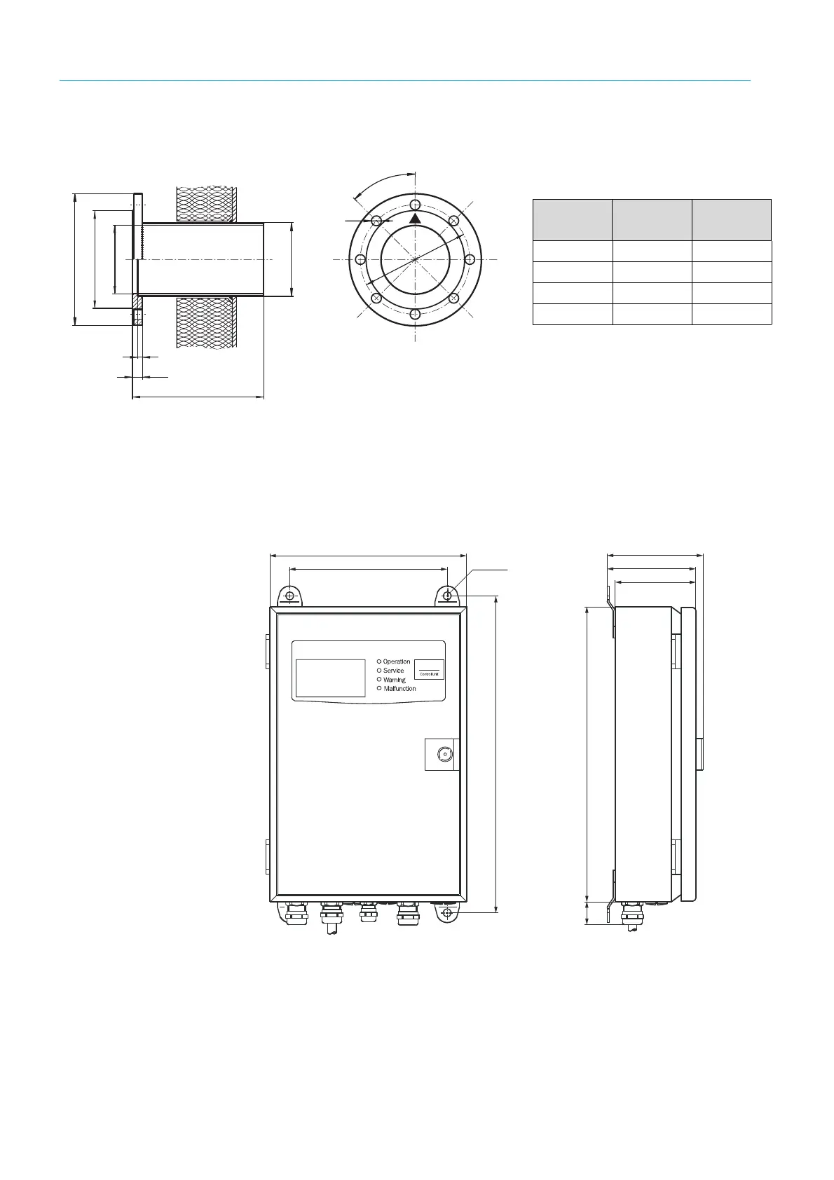
10.2.4 Flange with tube dimensions
Fig. 80: Flange with tube for installing the GM35 SR-unit on the duct
10.2.5 Dimension drawing of GM35 evaluation unit, sheet metal enclosure
Fig. 81: Dimensions of GM35 evaluation unit, sheet metal version
ø 240
ø 178
ø 125
ø 133
14
240/500
8
18
4
5
°
200
Versions deliverable from stock
Alternatively, an ANSI flange provided by the
customer can be used.
Part No. Material Length
[mm]
2016807 ST37 240
2016808 1.4571 240
2017785 ST37 500
2017786 1.4571 500
23
97,5
90
82
322
300
160
200
Ø 8

 Loading...


