Implementing all the safety functions for the application requires a complete system
consis
ting of sensors, a controller, actuators, and control switches. This safety system
comprises sensors and a controller only and is therefore only a subsystem. The require‐
ments for the additional components are defined in the system documentation. The
user is responsible for the safe design of the complete system and all safety functions.
The machine manufacturer must refer to the standard general guidelines for creating
safety functions within their application (see "Limits of the safety system", page 14).
3.4 Additional components required
The following components are also essential for using the safety system in an applica‐
t
ion:
•
Bar code tape
NOTE
All nece
ssary components, such as the drive and safety brake, influence the parame‐
ters of the entire application that relate to safety technology. The components must
therefore have an MTTF
d
value that is suitable for the entire application and satisfies
the necessary performance level. The necessary performance level results from the risk
assessment.
For evaluating the performance level achieved, subsystems for SISTEMA are available
under:
www.sick.com
3.4.1 Requirements for additional components required
All safety-related components must be checked to ensure that they are suitable for use
w
ith this safety system. This also applies to components that are not specified by this
safety system.
The safety values for the SLS request signal, the drive, the safe torque off (STO) function,
and the optional brake must be selected such that they at least comply with the PL e
general safety level. The structure must correspond to category 4.
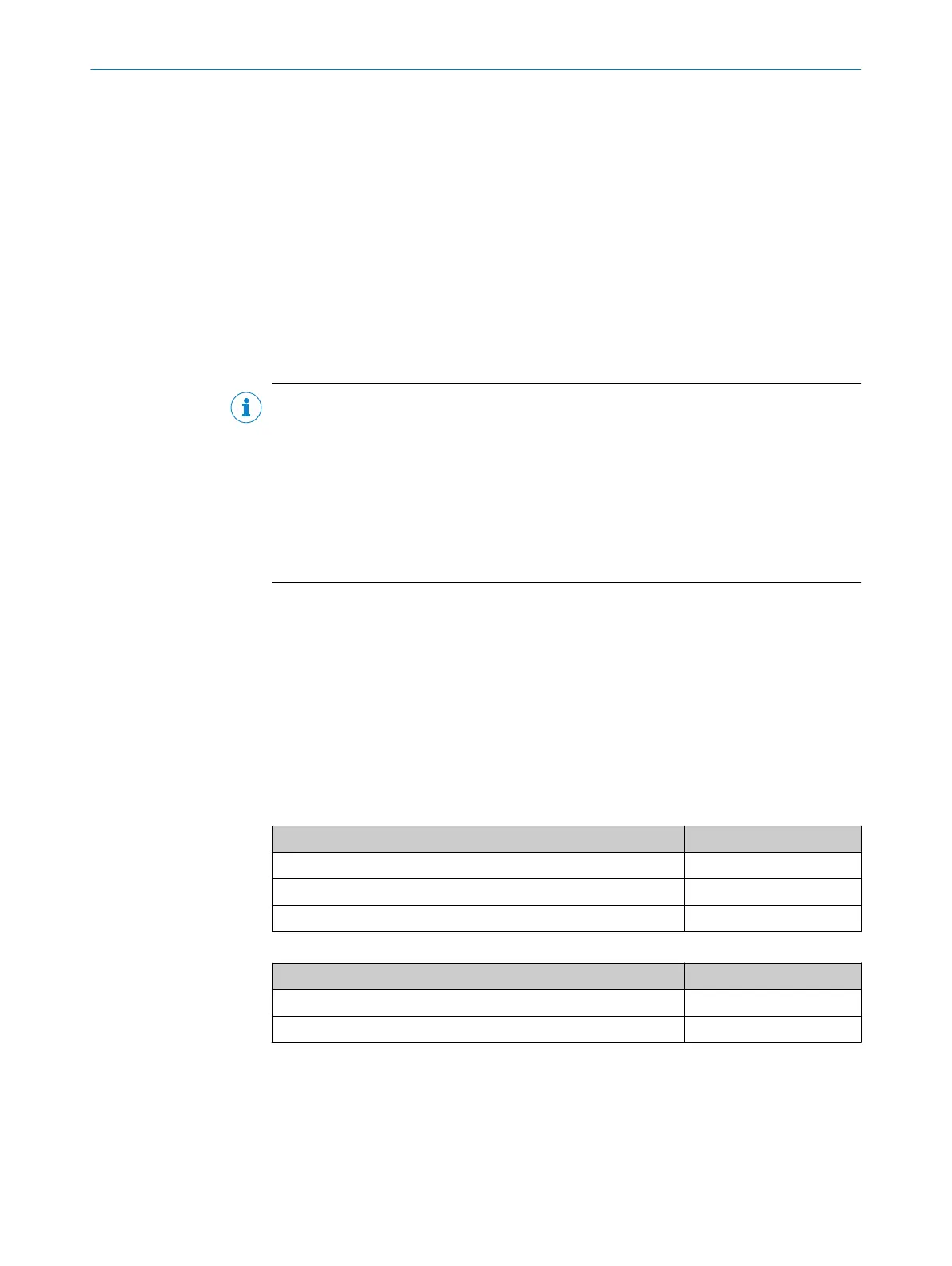
The following table shows e
xamples of PFH
D
values that allow for PL e to be reached.
Table 2: PFH
D
values when a brake is used (safe brake control)
Component PFH
D
v
alue
Subsystem T130: SL
S request signal PFH
D
≤ 6 x 10
-9
Subsystem R110 PDS (SR) - safe torque off (STO) function PFH
D
≤
2.2 x 10
-8
Subsystem R120 brake (optional) PFH
D
≤ 4 x 10
-8
Table 3: PFH
D
v
alues when a brake is not used (no safe brake control)
Component PFH
D
v
alue
Subsystem T130: SL
S request signal PFH
D
≤ 6 x 10
-9
Subsystem R110 PDS (SR) - safe torque off (STO) function PFH
D
≤
6.7 x 10
-8
If a safety brake (R120) is not used, the SL
S request signal (T130) and the safe torque
off (STO) function of the drive (R110) may have even worse PFH
D
values when it comes
to still reaching PL e.
3 P
RODUCT DESCRIPTION
12
O P E R A T I N G I N S T R U C T I O N S | Safe Linear Positioning 8020941/12O9/2019-08-05 | SICK
Subject to change without notice