7.4 Expanding and modifying the safety system
7.4.1 Configuring additional safety functions
Overview
Additional safety functions can be added to the safety system to trigger an SS1 or SS2.
Important information
DANGER
A
dditional safety functions are not part of this safety system.
The safety system may not function as intended after implementing additional safety
functions.
b
Only implement additional safety functions at your own risk.
b
Ensure that triggering of the safety function leads to appropriate behavior with
regards to resetting and restarting.
b
Ensure that the mechanisms are implemented correctly and that the safety func‐
tion is guaranteed.
Approach
1.
Move the mouse cursor to the Logic editor button.
2. Click on Logic editor.
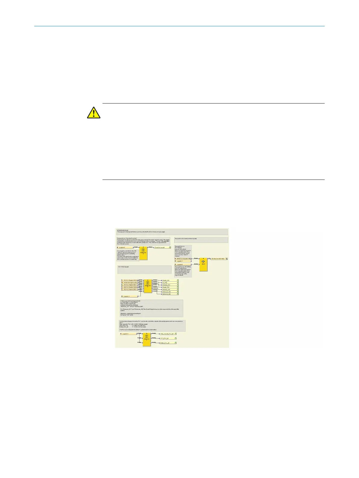
3. Click on the Interface logic page.
✓
The view opens. The page appears.
Figure 19: Request Safe Stop function block
4. Assign additional safety functions to the Ext
ernal_SS1 or External_SS2 jump
addresses.
5. Delete the link between static 1 and input 6 (for External_SS1) or input 7 (for Exter‐
nal_SS2).
6. Link the External_SS1 jump address to input 6 or External_SS2 to input 7 of the Rout‐
ing N:N function block.
Complementary information
•
Example: additional Safe Stop 1 requirement
CONFIGURATION 7
8020941/12O9/2019-08-05 | SICK O P E R A T I N G I N S T R U C T I O N S | Safe Linear Positioning
49
Subject to change without notice