5 Mounting
NOTE
Inf
ormation is included in the operating instructions for the components.
5.1 Mounting the sensor unit
The sensor unit is always fully mounted when delivered. It consists of two OLM 100 Hi
line
ar measurement sensors and a special mounting bracket. The sensors must not be
removed from the mounting bracket.
By using the mounting bracket and the safety screws for mounting, all of the mechani‐
cal requirements relevant to the system for the two sensors are taken care of in the
design and implemented. This reduces the risk posed by foreseeable misuse on the
part of the user and by manipulation.
The OLM100 Hi sensors are parameterized in advance and special firmware blocks
access so that parameters cannot be entered using the SOPAS ET software. Only the
approved sensors may be used.
The sensor system must be mounted such that the horizontal axis of the mounting
plate runs parallel to the bar code tape. The gap required between the sensor (front
screen) and the bar code tape must be between 80 mm and 120 mm. A distance of
between 100 mm and 110 mm is recommended.
WARNING
T
here is a risk of death or serious injury in the event of improper mounting as diagnos‐
tic action cannot be performed reliably.
b
Comply with the mounting distance stipulated.
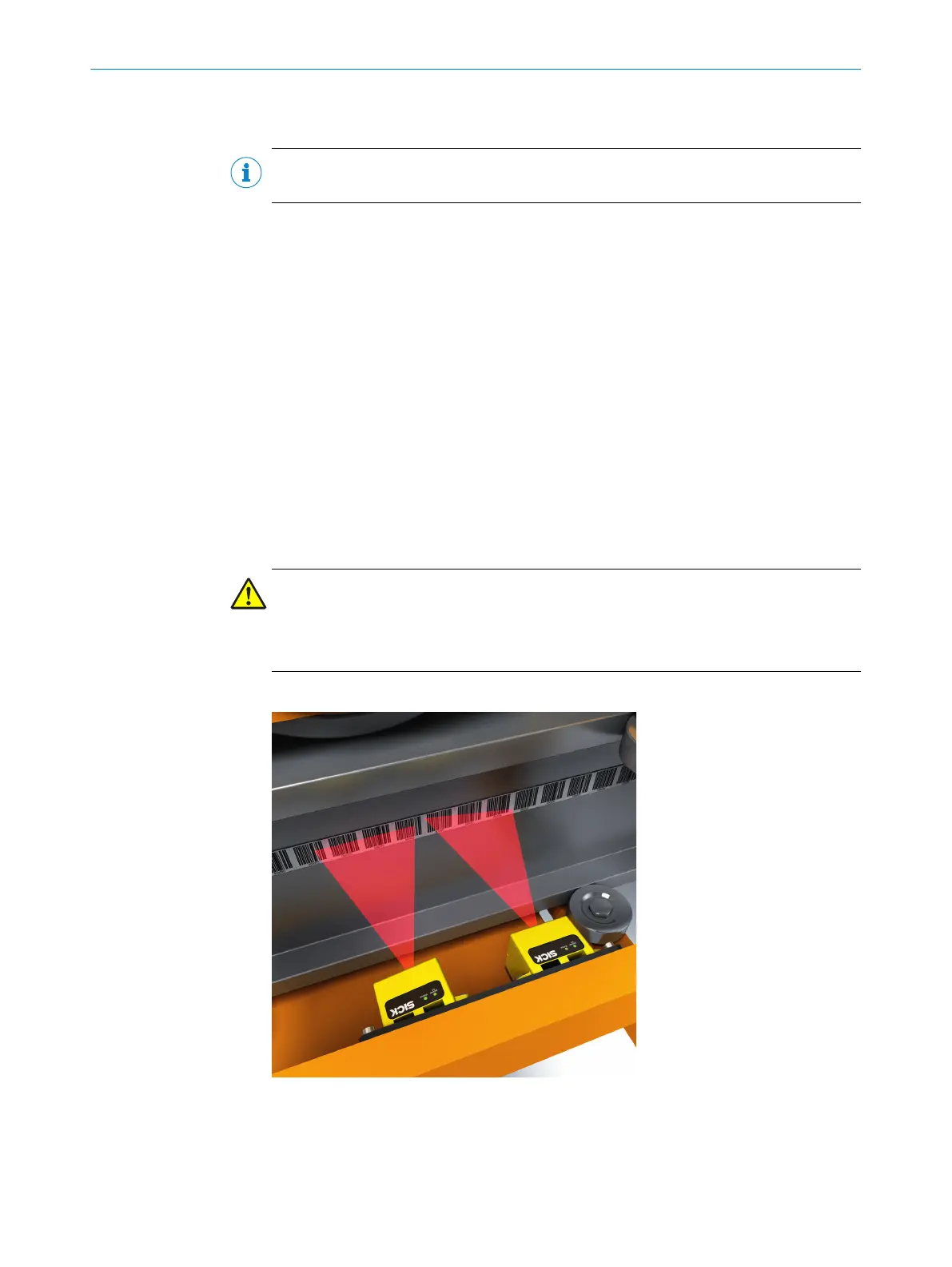
The beams from the sensor lighting must be positioned centrally on the bar code tape.
Figure 3: Distance between sensor and bar code tape
If t
he bar code height is 30 mm, the distance between the lower edge of the mounting
plate and the lower edge of the bar code tape must be 22 mm.
MOUNTING 5
8020941/12O9/2019-08-05 | SICK O P E R A T I N G I N S T R U C T I O N S | Safe Linear Positioning
21
Subject to change without notice