Module 3: outputs
T
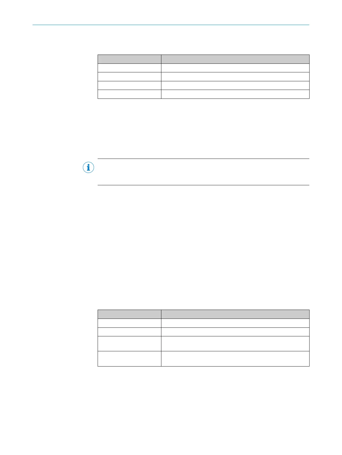
able 10: Function of the connections
Connection Function
Q1 QA120.1 brake (optional)
Q2 QA120.2 brake (optional)
Q3 H210.1 “Reset required” light (optional)
Q4 H210.2 “Restart required” light (optional)
6.4 Interfaces and signals
The safety system has both safety interfaces and standard interfaces. The Flexi Soft
out
puts that signal the safe state are considered to be safety interfaces, while those
used for test signals and the position value are considered to be standard interfaces.
6.4.1 Standard input interface: test signals
NOTE
T
he signals must be compatible with the inputs of the Flexi Soft XTIO module (see
"Technical data", page 78).
The position values of the sensors are compared with test signals from the non-safe
pr
ocess controller to cover faults occurring at the same time in both channels of the
redundant dual-channel sensor system (plausibility check). The direction signals from
the drive system or process controller are used as test signals. In this case, the Flexi
Soft safety controller always anticipates a notification of a change to the movement
direction from the process in the form of the corresponding status of the test signals
immediately before the change is made.
The test signals must be generated independently of the position data of this safety
system (OLM sensor 1). The test signals must be transmitted to the Flexi Soft safety
controller via two separate signal cables.
Definition of test signals
•
Test signal 1 active and test signal 2 active = standstill
•
Test signal 1 active and test signal 2 inactive = forward movement
•
Test signal 1 inactive and test signal 2 active = backward movement
•
Test signal 1 inactive and test signal 2 inactive = “safe state” request
Table 11: Meaning of signals
Signal Meaning
Active 24 V are applied to the input of the Flexi Soft controller.
Inactive 0 V are applied to the input of the Flexi Soft controller.
Forward Movement is taking place in the direction of ascending position
v
alues.
Backward Movement is taking place in the direction of descending position
values.
Both signal cables must not be inactive at the same time, so the safe state is initiated
in t
his case. This allows for cable breaks and the like to be detected.
6 ELE
CTRICAL INSTALLATION
28
O P E R A T I N G I N S T R U C T I O N S | Safe Linear Positioning 8020941/12O9/2019-08-05 | SICK
Subject to change without notice