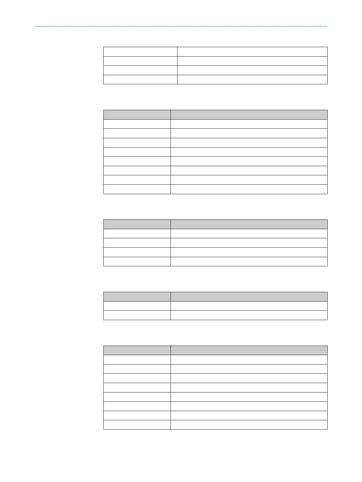
Table 5: Modules of the safety controller
Module 0 Main module FX3-CPUx
Module 1 I/O module FX3-XTIO
Module 2 Motion control module FX3-MOC1
Module 3 I/O module FX3-XTIO
Module 1: inputs
T
able 6: Function of the connections
Connection Function
l1 KF100.1 test signal 1
l2 KF100.2 test signal 2
l3 BG100.1.1 OLM sensor ID 1
l4 BG100.2.1 OLM sensor ID 2
l5 B130 SL
S request signal
l6 B130 SLS request signal
l7 SF200 emergency stop pushbutton
l8 SF200 emergency stop pushbutton
Module 1: outputs
T
able 7: Function of the connections
Connection Function
Q1 QA110.1 safety output (STO)
Q2 QA110.2 safety output (STO)
Q3 BG100.2.2 sensor 2 test request
Q4 KF130 stop request
Module 2: inputs
T
able 8: Function of the connections
Connection Function
Enc1 BG100.1 OLM sensor 1
Enc2 BG100.2 OLM sensor 2
Module 3: inputs
T
able 9: Function of the connections
Connection Function
l1 SF210.1 reset button
l2 SF210.2 start button
l3 Vacant
l4 Vacant
l5 Vacant
l6 Vacant
l7 Vacant
l8 Vacant
ELECTRICAL INSTALLATION 6
8020941/12O9/2019-08-05 | SICK O P E R A T I N G I N S T R U C T I O N S | Safe Linear Positioning
27
Subject to change without notice