The test signals from the process controller are used to check the plausibility of the
dir
ection of movement and standstill (see "Interfaces and signals", page 28).
OLM 1 is the leading sensor within this sensor system. Its position data is used within
the Flexi Soft safety controller, e.g., to monitor a safely delimited position and to poten‐
tially also monitor the speed. It is connected to the ENC1 input of the FX3-MOC1 mod‐
ule, and its position data is used by the FX3-MOC1 and by the process controller via a
splitter in the X-junction. This means that the user of the safety system has the option
of configuring the ENC1 input of the FX3-MOC1 as an SSI master or SSI listener in line
with the application in question.
OLM 2 is connected only to the ENC2 input of the FX3-MOC1 module, meaning that the
ENC2 interface is configured as an SSI master. The position data from OLM 2 is used
for testing and diagnostic action.
The linear measurement sensors are numbered when the X-junction is connected. The
connector plug for the OLM 2 has a colored mark and must be connected to the linear
measurement sensor for which the bar code tape displays a higher position value.
The two linear measurement sensors (OLM 1 and 2) output a code via the sensor ID
signals that can be used by the Flexi Soft safety controller to identify them.
3.6 Limits of the safety system
The system represents the part of the safety chain (partial safety function) that com‐
bine
s the sensor and logic. This does not, however, rule out the possibility of expanding
the chain with additional logic elements (e.g., a higher-level control). The output switch‐
ing elements of the Flexi Soft can also be used to control actuators.
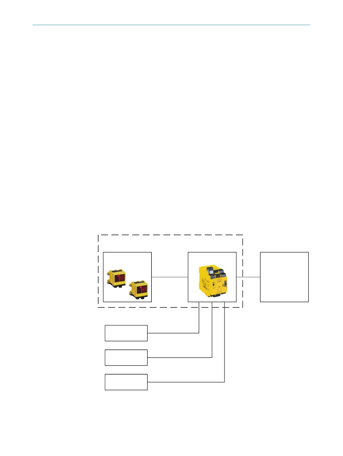
The block diagram illustrates the limits of the safety system. For the user, they end at
the terminals of the Flexi Soft controller.
Figure 2: Block diagram for the safety chain
1
Sensor
2
Flexi Soft safety controller
3
Actuator
3 PRODUCT DESCRIPTION
14
O P E R A T I N G I N S T R U C T I O N S | Safe Linear Positioning 8020941/12O9/2019-08-05 | SICK
Subject to change without notice