The default setting for the Speed F
ilter parameter is 10 mm and this must be taken into
account at the planning stage (see "Configuring speed limits", page 37).
WARNING
T
here is a risk of death or serious injury if the stopping distance is calculated incor‐
rectly.
b
Do not change the Speed Filter parameter.
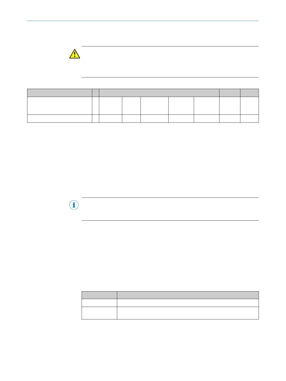
Table 69: Explanation of calculation formula
T t
1
t
2
Overall stopping time Sensor MOC
input
Max. data
reception
interval
MOC logic Flexi Soft
cycle time
Output Drive
47.5 ms + T
R
ampDelay
+ T
PDS(RS)
= 10 ms + 9 ms + 8 ms + T
RampDelay
+ 16 ms + 4.5 ms + T
PDS(SR)
T
R
ampDelay
An additional T
RampDelay
delay time may be required depending on the drive system in
use. This delay time, which can be adjusted in Flexi Soft, delays the start of ramp moni‐
toring. The delay time must correspond to the response time of the drive.
T
P
DS(SR)
T
PDS(SR)
is the amount of time required by the drive system for a stop ramp. If after t
1
the
acceleration is not great enough owing to a fault, the torque will be deactivated (safe
torque off, STO - stop). If the optional safe brake control (SBC) (QA120) is linked to Flexi
Soft, this will be activated too.
NOTE
If t
he stopping time with safe torque off (STO) and safe brake control (SBC) is greater
than in the case of the standard stop ramp, the higher value must be used for T
PDS(SR)
.
13.4.1 Stopping time in the event of a drive fault
If the drive is faulty and the speed is not limited, the torque is deactivated and the
opt
ional safe brake control (SBC) is activated.
T = t
1
+ t
2
t
1
= 47.5 ms + T
RampDelay
+47.5 ms
t
2
= T
brake
T = 95 s + T
RampDelay
+ T
brake
Table 70: Definition of operands
Code Meaning
T
brak
e
The amount of time the brake needs to stop movement.
T
R
ampDelay
Additional delay time that may be necessary depending on the drive system
in use.
13.4.2 Flexi Soft cycle time
The cycle time of the Flexi Soft safety controller is dependent on the scope of the logic.
In t
his document, the stopping time is calculated on the basis of a standard cycle time
of 8 ms.
TECHNICAL DATA 13
8020941/12O9/2019-08-05 | SICK O P E R A T I N G I N S T R U C T I O N S | Safe Linear Positioning
81
Subject to change without notice