7.3.7 Configuring stop ramps
The S
afe Stop function block of the MOC module is used to trigger and monitor the safe
stop of a drive system. The drive has to be stopped in a controlled way. The braking
torque of the drive can be used to stop the drive more quickly than would be possible in
the case of an uncontrolled stop.
The Safe Stop function block initiates the stop ramp and monitors to check that the
speed reduction is within the permitted range. This corresponds to the SS1-r/SS2-r stop
functions as per IEC 61800-5-2 and stop category 1/stop category 2 as per
IEC 60204-1.
Monitoring of stop ramps is not configured within the default settings for the Flexi Soft
software project. This means that without any further configuration the safe torque off
(STO) stop function as per IEC 61800-5-2 or stop category 0 as per IEC 60204-1 is per‐
formed in the event of a stop request.
1. Move the mouse cursor to the Logic editor button.
2. Click on K110-2 / MOC1 - Logic editor.
3. Select the Safe_Stop logic page.
✓
The view opens. The Safe_Stop page appears.
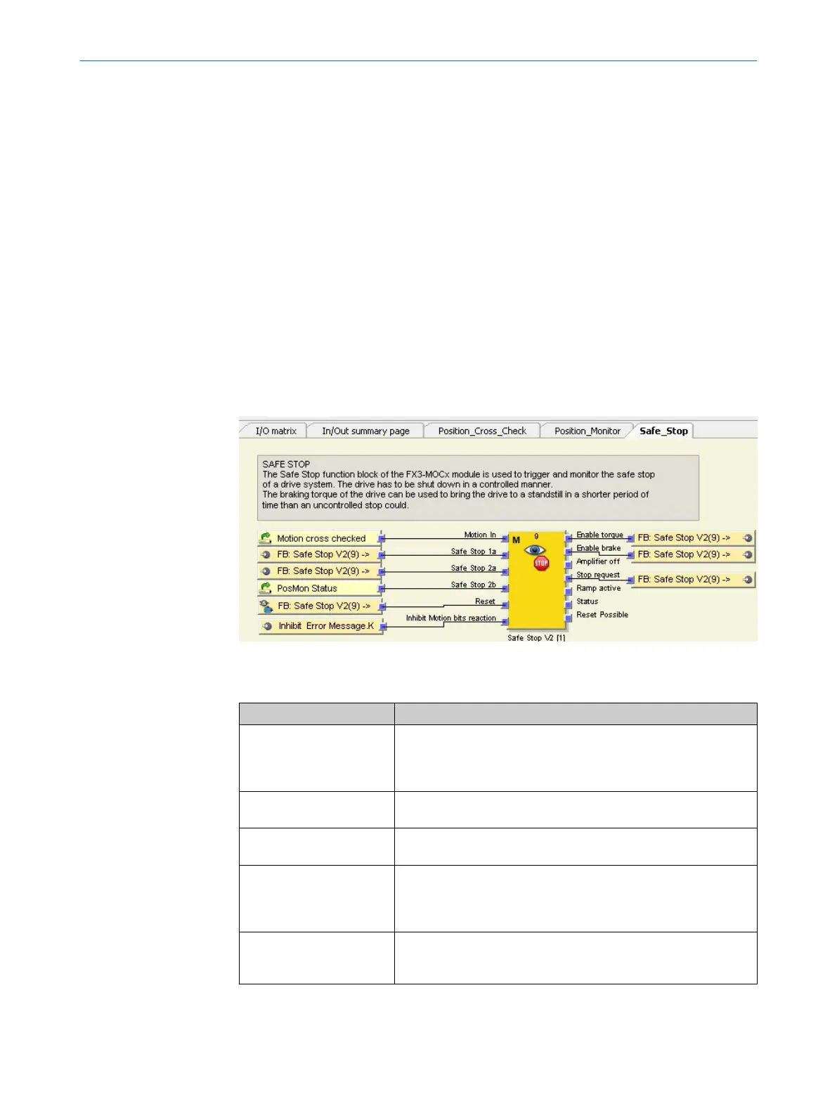
Figure 15: Safe Stop page view
T
able 35: Inputs of the function block
Input name Function
Motion IN This input receives the Mo
tion signal from the Position Cross Check
function block. A fault is detected as soon as the position data
from the sensor is no longer reliable. This signal will trigger a safe
stop 2 (SS2) at the Safe Stop function block.
Safe Stop 1a The SS1 request LowActive signal from the CPU logic is linked to this
input. If the signal switches to Low, a safe stop 1 (SS1) is initiated.
Safe Stop 2a The SS2 request LowActive signal from the CPU logic is linked to this
input. If the signal switches to Low, a safe stop 2 (SS2) is initiated.
Safe Stop 2b The P
osMon Status signal (status of the Position Monitor function
block) is linked to this input. If the current position is not permitted
or if the speed exceeds the safe limit, this signal will be set to Low
and a safe stop 2 (SS2) will be initiated.
Reset The reset signal comes from the CPU logic. A reset signal is
required following a safe stop 2 (SS2) or in order to reset the func‐
tion block after a fault has occurred.
1
CONFIGURATION 7
8020941/12O9/2019-08-05 | SICK O P E R A T I N G I N S T R U C T I O N S | Safe Linear Positioning
45
Subject to change without notice