NOTE
T
he user of this safety system must ensure that all components used comply with the
requirements of category 4, PL e in accordance with EN ISO 13849-1 (or SILCL3 in
accordance with EN 62061).
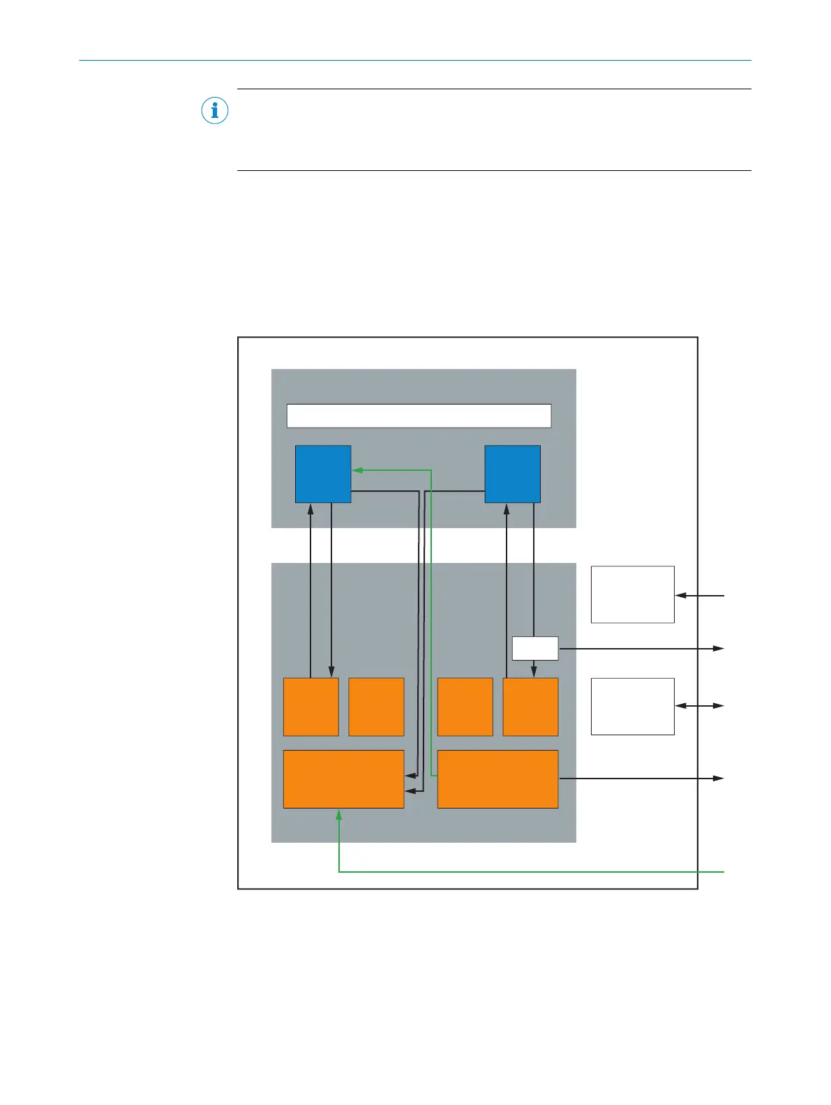
3.5 Structure and function
On the sensor side, the safety system consists of two OLM100 Hi linear measurement
sensor
s with a shared bar code tape. On the controller side, the system consists of the
safe Flexi Soft controller, which is made up of the CPU main module, safe XTIO I/O mod‐
ule, and the FX3-MOC1 Drive Monitor module.
The complete system is divided up into the sensor and controller main modules, which
include submodules and general functional modules.
Sensor
Bar code tape measure
OLM 2
MOC 1
Assessment
Input XTIO
Assessment
Output XTIO
Assessment
MOC 1
Assessment
CPU
Safe
Control
Logistics
CPU
Safe
Control
Logistics
OLM 1
Voltage
suppl
y
Communication
Control
Splitter
SSI
SSI
SSI
Voltage supply
Voltage supply
SensorIDs
Test request
Control
Safe outputs
Test signal (from the process)
Figure 1: System concept
T
he rail system of the linear drive has a bar code tape, e.g., on the mounting rail. Bar
codes are printed onto the bar code tape at fixed distances with linearly increasing dis‐
tance information. The two OLM100 Hi linear measurement sensors read the bar codes
at each position independently. The motion control module of the safety controller uses
the rate of change of the positions read to determine the vehicle’s speed and direction
of travel.
PRODUCT DESCRIPTION 3
8020941/12O9/2019-08-05 | SICK O P E R A T I N G I N S T R U C T I O N S | Safe Linear Positioning
13
Subject to change without notice