13.3 Dimensional drawings
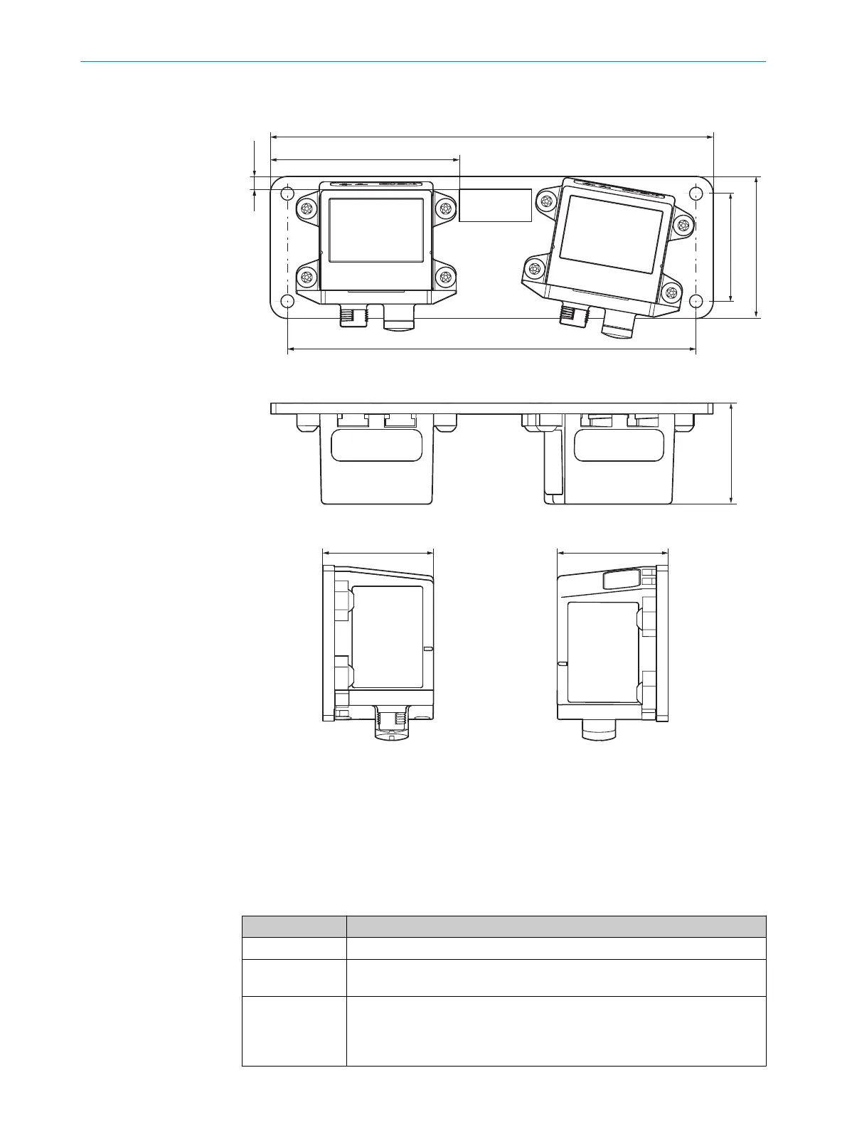
88 ±1
206 ±0.2
47 47
190 ±0.2
6 ±1)
50 ±0.2
66 ±0.2
47
Figure 49: Dimensional drawing for the OLM100 Hi on a mounting plate
13.4 Response times
Overrun for the entire system
T
he overrun for the entire system is made up of at least two phases.
T = t
1
+ t
2
Table 68: Calculation of overrun for the entire system
Code Meaning
T Overrun for the entire system
t
1
Maximum amount of time between the protective device being activated
and t
he OFF state of the output being reached.
t
2
The maximum amount of stopping time required to end the dangerous sta‐
t
us of the machine once the output signal from the protective device has
been switched to the OFF state. The response time of the machine’s control
system must be taken into consideration when calculating t
2
.
13 TECHNICAL DATA
80
O P E R A T I N G I N S T R U C T I O N S | Safe Linear Positioning 8020941/12O9/2019-08-05 | SICK
Subject to change without notice