7.4.4 Controlling the safety outputs directly via PLC
Important information
DANGER
This safety system does not include the ability to control the safety outputs directly
using process signals.
Implementation of the adaptation described in this chapter makes you the manufac‐
turer of a safety system.
1. Carry out the adaptation of the safety system described here only subject to own
responsibility.
2. Comply with all manufacturer obligations for development and implementation of
a safety system.
Approach
T
his modification allows the PLC to switch the safety outputs in the safety system to a
safe state at any time. This does not circumvent the safety functions.
1. Move the mouse cursor to the Logic editor button.
2. Click on Logic editor.
3. Click on the Interface logic page.
✓
The view opens. The page appears.
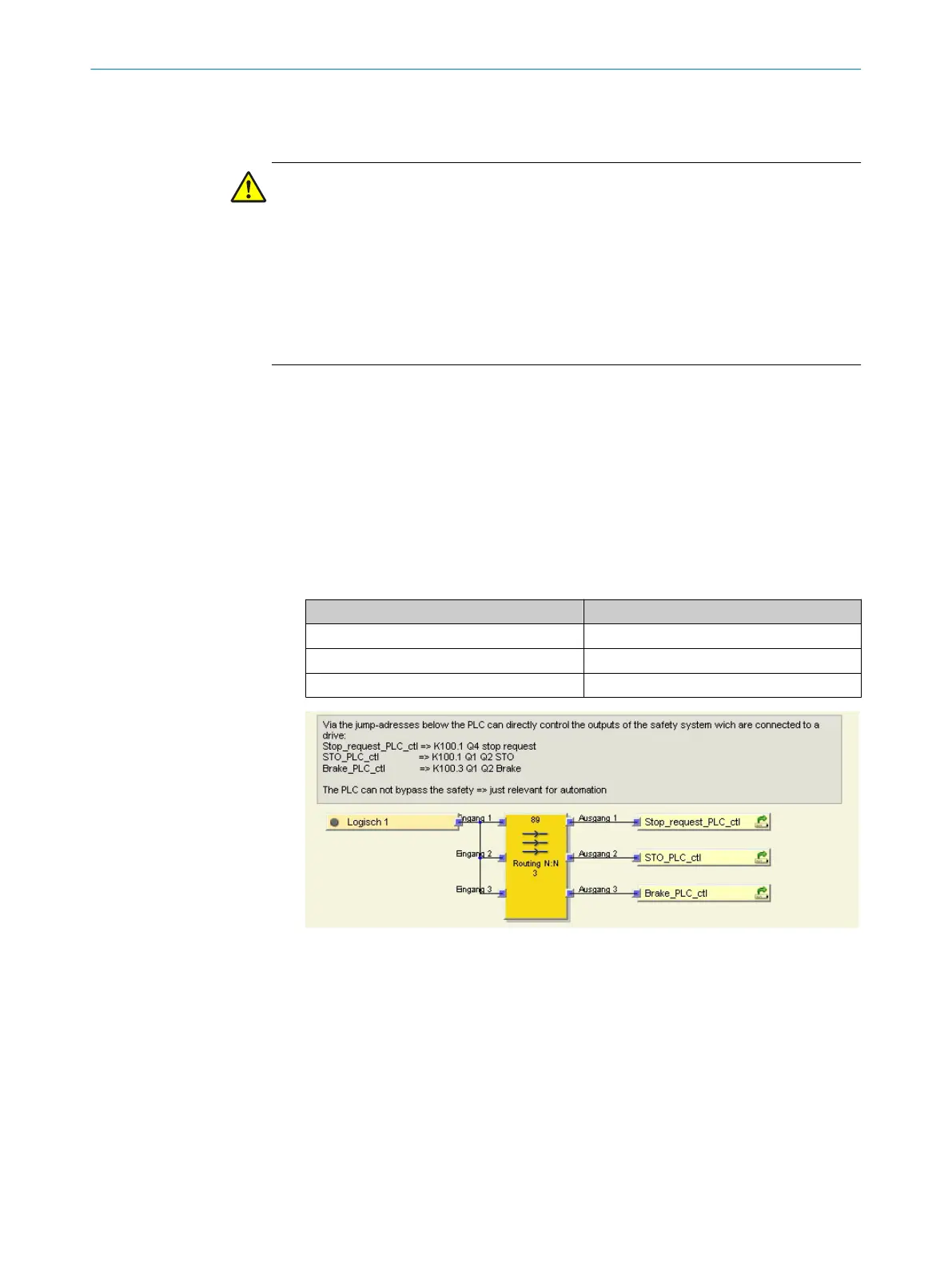
4. Replace Static 1 with signals intended to control the individual outputs. This
involves the following assignment between the jump address and safety output:
Table 40: Assignment of jump address and safety output
Jump address Safety output
Stop_request_PLC_ctl K100.1 Q4 stop request
STO_PLC_ctl K100.1 Q1 Q2 STO
Brake_PLC_ctl K100.3 Q1 Q2 Brake
Figure 24: Function block view – Routing
Complementary information
C
ontrolling the safety outputs directly can, for example, help to control the brake if this
is also to be used as a retaining brake
7.4.5 Use of internal status information
Overview
Jum
p addresses provide internal status information that can be used in the application.
CONFIGURATION 7
8020941/12O9/2019-08-05 | SICK O P E R A T I N G I N S T R U C T I O N S | Safe Linear Positioning
53
Subject to change without notice