This page contains the following function blocks:
•
S
afe Stop 1: Reset and Restart
•
Safe Stop 2: Reset and Restart
•
User-defined function block used to control a light for two function blocks for reset‐
ting and restarting
7.5.5.1 Reset for Safe Stop 1 function block
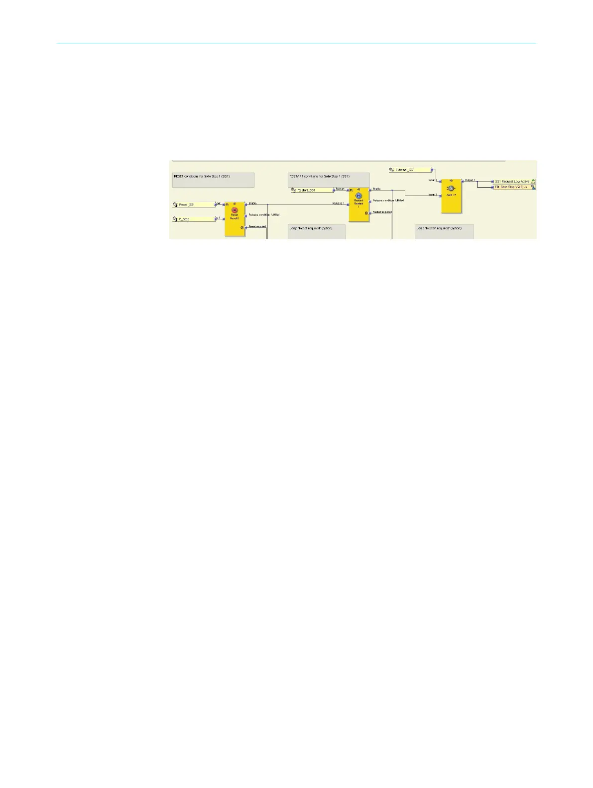
Figure 37: Function block view - Reset for Safe Stop 1
W
ith the Reset function block, the requirements of the safety application are fulfilled as
set out by the EN ISO 13849-1 standard for detecting a manual safety stop with a sub‐
sequent request to restart the application.
As soon as E_Stop is no longer set to High, Safe Stop 1 is initiated.
If the E_Stop input is set to High, the release condition has been met. A reset signal
(Reset_SS1) with a pulse duration of at least 100 ms sets the Enable output to High. This
is a release condition for the Restart function block.
The Enable and Reset required outputs are used in order to use the optional H210.1 Reset
required light by means of the user-defined Lamp reset/restart required function block.
7.5.5.2 Restart for Safe Stop 1 function block
The R
estart function block allows for a graphical distinction to be made between the
function blocks.
As soon as the Release 1 input is no longer set to High, it initiates the Safe Stop 1 func‐
tion.
A valid reset sequence at the Reset function block is required in order for a restart to be
performed.
If the Release input is set to High, the release condition has been met. The Enable output
is set to High when a restart signal (Restart_SS1) lasts for a pulse duration of at least
100 ms.
The Enable output is linked to the MOC1 logic via an AND function block in order to initi‐
ate the Safe Stop 1 function with the Safe Stop function block. The output is also linked
to the SS1 Request LowActive jump address, which notifies other parts of the CPU logic
that a Safe Stop 1 request has been issued.
7.5.5.3 Triggering a Safe Stop 1 with additional safety functions
The Safe Stop 1 function can also be triggered by additional safety functions. The
AND f
unction block connects additional safety functions via the Input 1 input, which is
linked to the External_SS1 jump address.
Further topics
•
"Ext
ension and modification", page 19
•
"Configuring additional safety functions", page 49
7 C
ONFIGURATION
62
O P E R A T I N G I N S T R U C T I O N S | Safe Linear Positioning 8020941/12O9/2019-08-05 | SICK
Subject to change without notice
 Loading...


