2 - 23
Installation
SETTING THE MODE OF OPERATION - CSM-4
(USING S3, S4 AND G1, G2)
For Circuit 1
S3
Position G1
Notification Appliance Circuits
Municipal Tie (NFPA 72B)
Remote Station (NFPA 72C)
Releasing Service (NFPA 12A)*
Releasing Service (NFPA 13)*
Releasing Service (NFPA 2001)*
Illegal (Results in a trouble on CSM-4)
1
1
2
1
1
1
2
Not Cut
Cut
Not Cut
Cut
Cut
Cut
Cut
For Circuit 2
S4
Position G2
Notification Appliance Circuits
Municipal Tie (NFPA 72B)
Remote Station (NFPA 72C)
Releasing Service (NFPA 12A)*
Releasing Service (NFPA 13)*
Releasing Service (NFPA 2001)*
Illegal (Results in a trouble on CSM-4)
1
1
2
1
1
1
2
Not Cut
Cut
Not Cut
Cut
Cut
Cut
Cut
*CANADA ONLY: Do not cut jumpers G1 and G2 for
NFPA 12A, NFPA 13, and NFPA 2001.
72 Municipal Tie, 72 Remote Station
(leased line), and NFPA 12A, NFPA 13,
and NFPA 2001 (releasing service).
Each circuit on the CSM-4 can be set
independently for the type of operation
desired. The table above shows how
to set the switches and jumpers for
circuits 1 and 2. The CSG-M printout
shows the mode for each circuit.
Set the Degrade Modes of Operation
There are two sources of degrade
activation, the degrade alarm bus and
the degrade trouble bus. These two
buses become active ONLY when the
MXL communication network fails.
Switch S2 on the CSM-4 sets the
degrade mode of operation for each
circuit.
Each circuit operates independently in
the degrade mode. Switch S2, posi-
tions SW1 and SW2, determines the
degrade mode of operation when the
trouble bus activates. S2, positions
SW3-SW6, determines the degrade
mode of operation when the alarm bus
activates.
Degrade Trouble Activation
The degrade trouble bus may ONLY be
used when the circuit is used as a
leased line trouble circuit (NFPA 72
Remote Station). When enabled, this
trouble default mode ensures that a
trouble is transmitted to the receiving
station even when the MXL communi-
cation network fails.
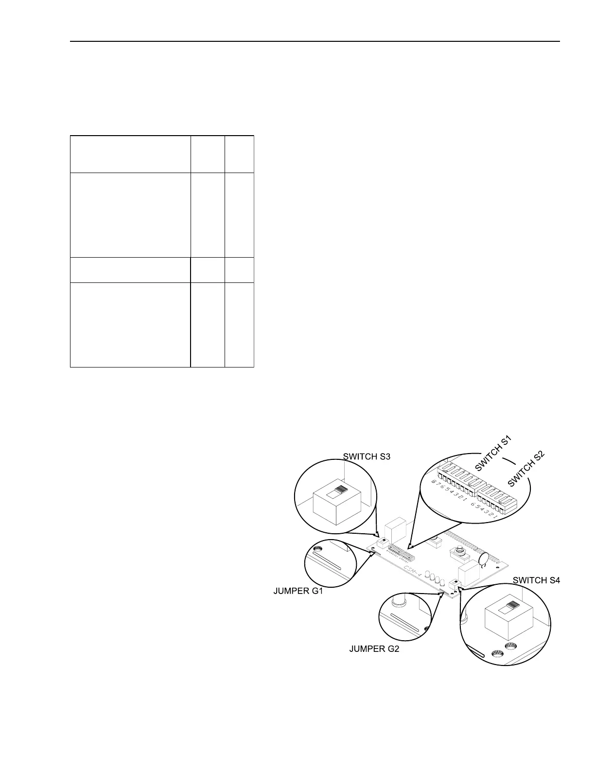
Switches and Jumpers on the CSM-4
Technical Manuals Online! - http://www.tech-man.com

 Loading...


