119 / 244
Siemens Standard application AHU CE1P3977en_02
Building Technologies Communication 01.02.2010
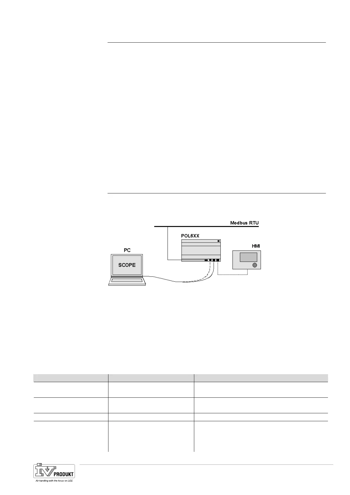
9.2 Modbus
Two Modbus interfaces are always available on the basis controller. The RS485
interface can be defined as master or slave. The MODBUS-IP interface is always a
slave. Both interfaces can be switched off jointly.
The internal RS485 Modbus interface is automatically set to master if the Energy
meter function is enabled.
A slave interface is always provided with the external Modbus communications
module POL902. The setting Slave Type switches the size of the interface from
simple to advanced (more values on the bus).
The internal cannot be used if the external module is used and the internal inter-
face is not required as master; the must be connected to terminal T1 of the com-
munication module.
The interface for the Modbus now uses the complete register range from both
channels on channel 0 (even more values than for the internal Modbus in the Ad-
vanced position). As a result, channel 2 (terminal T2) can no longer be used.
9.2.1 Commissioning the internal Modbus
Participating devices
− Climatix POL 636 controller.
Prerequisites for commissioning:
– Working application (e.g. standard AHU application) loaded and started in the
Climatix controller.
– Corresponding mapping file (OBH.bin) is loaded. This is the only way the con-
nection to the Modbus is available.
Main Index > Integrations
Parameter Range Function
Energy meter EM24 − No
− Yes
No energy meter selected.
Settings Go to page with all parameterization for the en-
ergy meter or the RS485 MODBUS settings.
Inputs Go to page with inputs.
Room units − 1 sensor
− 2 sensors
− 1 RU
− 1snsr+ RU
Inputs for room temperature sensor. You can
select whether to apply maximum, minimum,
average or individual value for control for more
than one sensor in Configuration 2. When select-
Internal interface
External communications
module
Devices
Prerequisites
Configure internal
Modbus interface for
EM24
Basis Document Siemens Climatix Control System
BDCX.100820.01GB
Page 119

 Loading...