14 / 244
Siemens Standard application AHU CE1P3977en_02
Building Technologies Function overview 01.02.2010
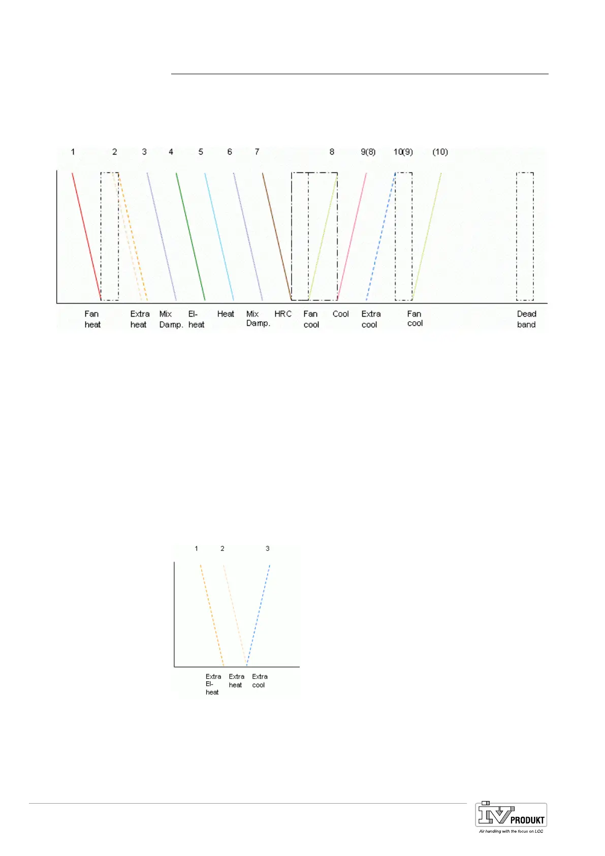
3.3 Workflow diagram
• Mixing dampers have changeable placement.
• Fan cooling have changeable placement.
• Deadband between heating and cooling can be changed.
• Fanheat and Fancool have their own changeable deadband.
The figure displays a schematic of all possible sequences included in the applica-
tion. Individual sequences and series are set automatically during configuration or
for sequence 3, 6 mix damper and 8, 9 fan cool, cooling by configuring the sequen-
ce.
1 Fan heating 7 Heat recovery
2 Heating 2 or Electro heating 2 8 Fan cooling
3 Mixing dampers 9 (8) Cooling
4 Electro Heating 10(9) Cooling 2
5 Heating (10) Fan cooling
6 Mixing dampers DB Dead band
Extra sequences can be placed in the normal sequence (above) or as an own
sequence (stand alone):
1 Electro Heating 2
2 Heating 2
3 Cooling 2
With all aggregates
Legend
Stand alone
Legend
Basis Document Siemens Climatix Control System
BDCX.100820.01GB
Page 14

 Loading...