178 / 244
Siemens Standard application AHU CE1P3977en_02
Building Technologies HMI 01.02.2010
17.4 Main overview
Diese Seite enthält eine Übersicht aller Hauptwerte der konfigurierten Applikation.
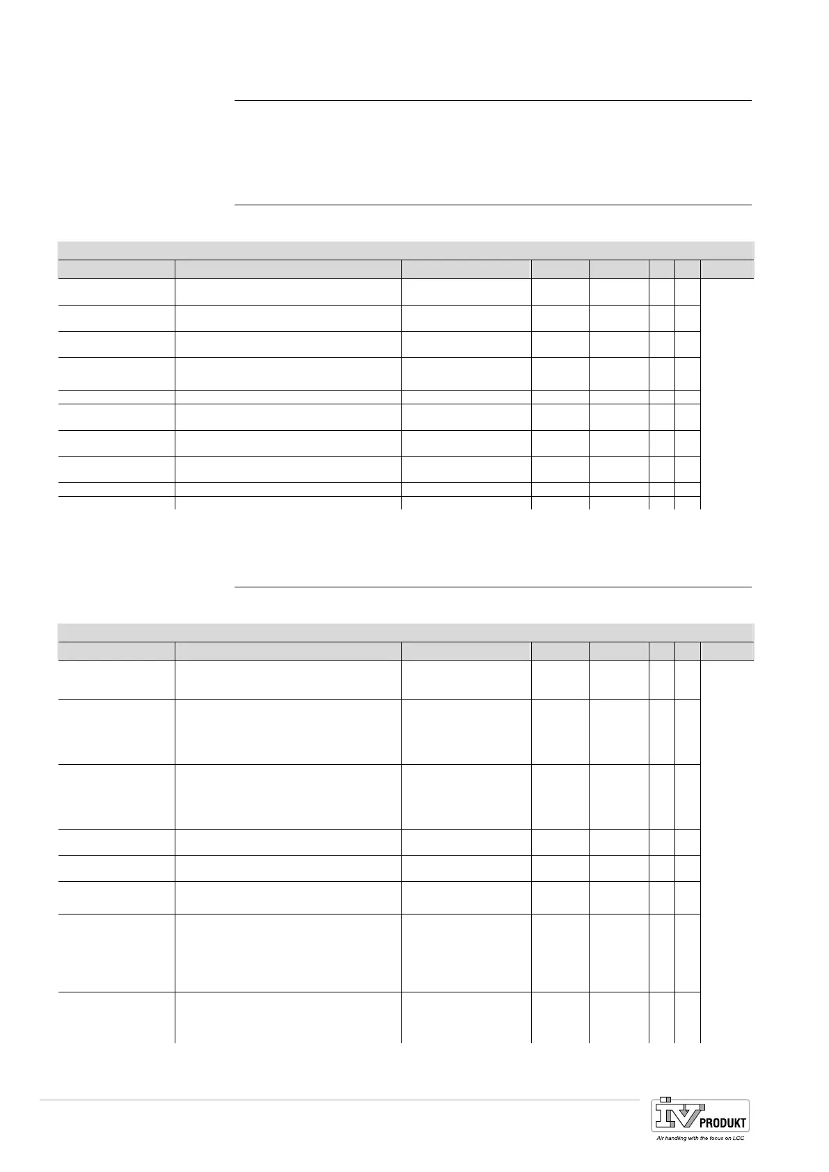
17.5 Configuration
Write access 4 required to go to this page.
Main Index > Configuration
Parameter Function Value range Unit Standard R S Link
Configuration by Choose the way of configuration
HMI Config
Download
Download 4
Configuration 1
Indicator if Configuration 1 is finished.
Jumpline to Configuration 1
NotDone
Done
4
Configuration 2
Indicator if Configuration 2 is finished.
Jumpline to Configuration 2
NotDone
Done
4
Configuration IO’s
Indicator if Configuration IO’s is finished.
Jumpline to the IO Configuration
NotDone
Done
4
Section:
15
Check Config IO’s Jumpline to the IO check
Doubled
If you have configured one In or Output more
than once, you get a Fault
OK.
Fault
Not Configured
If you have configured a function, and not
configured the needed IO’s you get a Fault.
OK.
Fault
Integrations
Jumpline to the configuration of the
communication
RoomUnit1 Jumpline to room Unit 1 (not implemented)
RoomUnit2 Jumpline to room Unit 2 (not implemented)
17.6 Configuration 1
Write access 4 required to go to this page.
Main Index > Configuration > Configuration 1 --- General
Parameter Function Value range Unit Standard R S Link
Extension modules Number of extension modules No
One
Two
No 4
Fire alarm Kind of Fire alarm
alarm = digital Input for alarm
tmp = Supply /Exhaust Temperatur are
supervised
alarm+tmp = both variants are active
No
alarm
tmp
alarm+tmp
No 4
Filter alarm Existing Filter alarms
Combined = one alarminput for both Filters
Supply = only Supply Filter
Exhaust = only Exhaust Filter
Sply+Exh = both Filter with separate Inputs
No
Combined
Supply
Exhaust
Supply+Exhaust
No 4
Emergency stop Digital Input Emergency stop No
Yes
Yes 4
alarm ackn input Digital Input for Alarm ackn button Button No
Yes
No 4
Su/Wi input Digital Input for Summer Winter Change over
TRUE = Summer
No
Yes
No 4 Section:
0
TSP function Select the needed Scheduler function
No = Scheduler disabled
Step = possible OpMode Off / [Number of
Steps selected in TSP Steps]
Step+tmp = possible OpMode Off/ [Number
os Modes selected in TSP Steps]
No
Step
Step+tmp
Step 4
TSP Steps If TSP function = Step: Number of Steps for
Fan
If Tsp Functon = Step+Temp: Number of
Setpoints (Off /Eco1-3 /Com1-3)
1Step
2Steps
3Steps
1St 4
Basis Document Siemens Climatix Control System
BDCX.100820.01GB
Page 178

 Loading...