181 / 244
Siemens Standard application AHU CE1P3977en_02
Building Technologies HMI 01.02.2010
Main Index > Configuration > Configuration 2
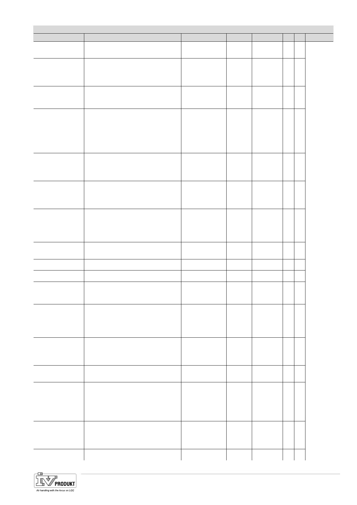
Parameter Function Value range Unit Standard R S Link
Damper fdbk Damper Feedback
Supply Damper fdbk (combined=1fdbk)
Exhaust Damper fdbk
No
One
Two
No 4
Fan steps freq conv Additionally digital Outputs for Frequency
controlled Fans
1step = Enable signal for FreqConv
2/3steps = extra DO’s can be used to switch
somthing according to the Fan step
1Step
2Steps
3Steps
1St 4
Flow display
Analog Input for Sensor to see the actual
Flow without any controlled Function
Analog Output for actual flow Value
No
Yes
Yes+Outp
No 4
Fan steps type Select hardware configuration of DO’s for
Fans
Sep = Single Output per Fan and Step
SepCombine = Single Output St1 per Fan,
St2 and Step3 one Output per Step for both
Fans
Binary= Single Outputs per Fan but binary
coded St3 = both DO per Fan are active
Sep
SepCombine
Binary
Sep 4
Fan alarm Combination and Type of Fan alarms
Combined = one alarm for both Fans
Supply = only Supply Fan alarm
Exhaust = only Exhaust fan alarm
Sply+Exh= two separate alarms
No
Combined
Supply
Exhaust
Sply+Exh
No 4
Fan fdbk Combination and Type of Fan Feedback
Combined = one fdbk for both Fans
Supply = only Supply Fan fdbk
Exhaust = only Exhaust fan fdbk
Sply+Exh= two separate fdbk’s
No
Combined
Supply
Exhaust
Sply+Exh
No 4
Fan deviation alarm Alarm if the Pressure/Flow Setpoint is not
reached
Supply = only Supply deviation alarm
Exhaust = only Exhaust deviation alarm
Sply+Exh= Supply and Exhaust deviation
alarms
No
Supply
Exhaust
Sply+Exh
No 4
Fan cmp room tmp Fan compensation according to Room or
Exhaust Temperature (only possible with
Room or Exhaust air sensor)
No
Yes
No 4
Fan cmp air qual Fan compensation according to Airquality
Control
No/Yes No 4
Fan cmp humidity Fan compensation according to Humidity
control
Fan cmp outs tmp Fan compensation according to Outside
Temperature
(only possible with Outside temperature
sensor)
No/Yes No 4
Fan htg / clg Influence the Fan according to the
Temperature sequence
Htg = influence as Heating Sequence
Clg = influence as Cooling Sequence
Htg+Clg = influence as Htg and Clg
Sequence
No
Htg
Clg/
Htg+Clg
No 4 Section:
15.2
Tmp stpt selection Setpoint selection for Cascade controller
Htg Setpoint + DB = Clg Setpoint
Separate Htg and Clg Setpoint
Basic Setpoint + ½ DB = Clg; - ½ DB = Htg
Clg Setpoint – DB = Htg Setpoint
HtgSpv+Dz
HtgClgSpv
Spv+HalfDz
ClgSpv-Dz
HtgSpv+DB
4
Ext stpt function Shift +/- x degrees of the Temperature
Setpoint
Override the Setpoint
Shift
Override
Shift 4
Room tmp mix Select the valid Room temperature for
controlling
(only possible if more than one Room
temperature available)
Average
Minimum
Maximum.
RoomSnsr1
RoomSnsr2
RoomUnit1
RoomUnit2
Average
Room draught limit No = The setted Min/Max Values from the
Temperature Cascade controller are Valid
FlowLim = you can set a max allowed
temperaturedeviation between the Supply
Air and the Room temperature
No
FlowLim
No
Sequence fan clg Fan Cooling order in Sequence (only
possible if Clg is selected)
Fan-Clg
Clg-Fan
Fan-Clg 4
Basis Document Siemens Climatix Control System
BDCX.100820.01GB
Page 181

 Loading...