Closed-loop thyristor current control
5-4 System- and communication configuring D7-SYS - SIMADYN D
Edition 06.2002
The interrupt, depending on the slot on the PM5/6 should be selected in
the "HW Config" software section.
The user should make the following settings.
• Interrupt tasks I1: LE bus interrupt L1 (ITDC in the 1
st
PM slot) or
LE bus interrupt L3 (ITDC in the 2
nd
PM slot)
• Equivalent sampling time 3.3 ms for 50 [Hz] line frequency
2.7 ms for 60 [Hz] line frequency
The following settings are made in the standard software package.
• Name: D01_P1 Processor 1 at slot 01
• Sampling time T0: 2.0 ms
• Name: D02_I1 ITDC module
Properties, ITDC: Addresses:
Digital inputs 1 D02_Bin
Speed sensing 1 D02_IncEnc
HW of the closed-loop thyristor current control D02_TCCONTR
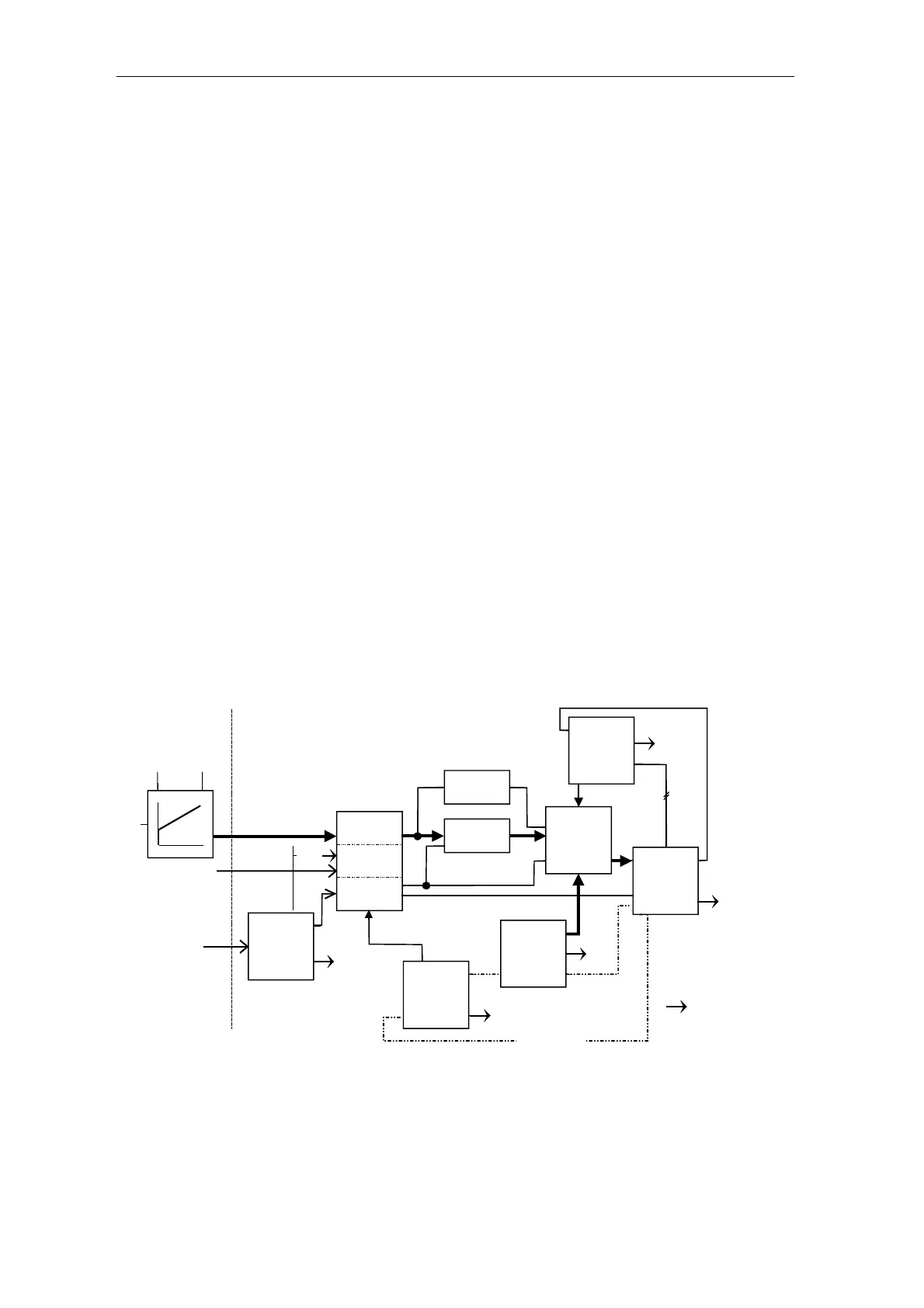
5.1.2 Software configuration
The software for the standard closed-loop thyristor current control
comprises the set from the converter-specific function blocks (FB).
The FBs are programmed in a standard function chart (CFC) for normal
applications of a DC drive.
The closed-loop current control should be integrated in the plant/system
software. Generally, there is a higher-level closed-loop and open-loop
speed control.
CSP 6
setp.smth.
FCS 3
field current
switch-on
CPC 7
dis.pre-ctrl.
SOL 4
setpoint
KP TN
EMF 2
volt.act.val.
EMF
generation
CAV 5
current
act. value
CPI 8
current
controller
PC6 9
Firing pulse
generation
PA6 1
Synchron.
Cyclic Interrupt
⇐
⇐
Fault
evaluation
Field current
QSF
Switch-on/
changeover
QSF
QSF
QSF
CAV
EMF
PA6
PC6
FCS
QSF
On
command from
the control
Setting command
Volt.V/f
Current V/f
Firing pul-
se output
Acknowledge
⇐
ITDC
Fault
⇐
Counter
⇐
⇐
Speed
control
Enable
QSx
Handshake
1-9 = Computation
sequence
Fig. 5-2 Overview of the software configuration
HW configuration