Communications configuring
3-162 System- and communication configuring D7-SYS - SIMADYN D
Edition 12.2003
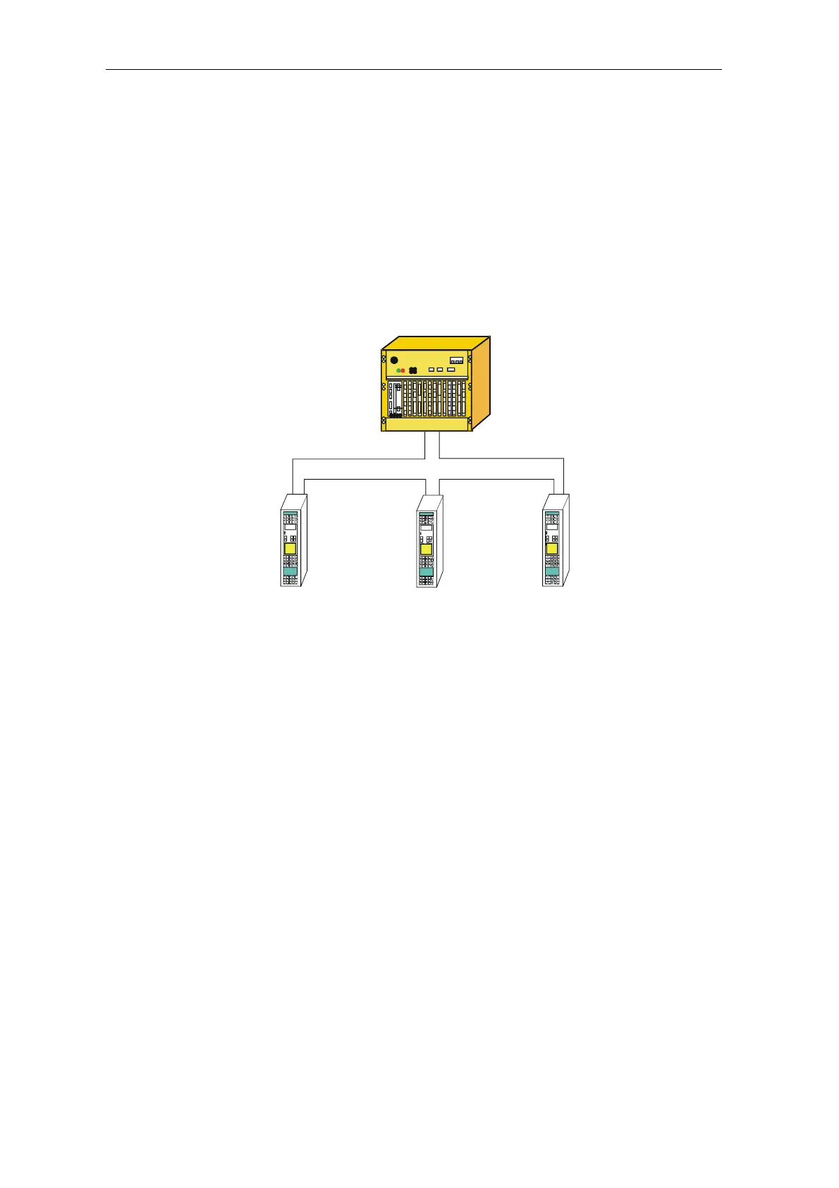
3.17.2 Application with master-slave process data transfer
The automation system with SIMOLINK interface is generally configured
as the SL master. Whereby, all of the other coupling nodes are set as
slaves/transceiver (refer to MASTERDRIVES option module SLB
SIMOLINK).
The number of channels used for each slave/transceiver is defined by the
SIMOLINK function blocks (connections CTV, CSV).
SIM
D
ND
SIEMENS
6SE7016- 1EA30
WR 2,2 kW
Nr. 4 67321
SIMOVERT SC
Transceiver
SIEMENS
6SE7016- 1E
30
WR2,2kW
Nr. 4 6 7321
SIMOVERT SC
Transceiver
SIEMENS
6SE7016- 1E
30
WR2,2 kW
Nr. 4 67321
SIMOVERT SC
Transceiver
SIMOLINK
Master
SIMATIC S7-400 oder SIMADYN D
Fig. 3-53 Application example for master-slave process data transfer
• The SL master can read and write into all of the channels of all of the
slaves/transceiver.
Configuring data:
Function block @SL: MOD connection = 1...5
For each slave: e.g. one SLSVAV
• Each slave can read all of the channels and write into a max. of 8
(
own!) channels.
Configuring data:
Function block @SL: MOD connection= 0
For each read channel: e.g. one SLAV
For each write channel: e.g. one SLSV,
Connection, FSL: Slave's
own address
Connection, NSL: 1
• In order to transfer data from slaves/transceivers to
slaves/transceivers which are physically located in front in the ring, in
the same bus cycle, the slave-to-slave communications setting must
be used.
Configuring data:
Function blocks SLAV and SLDIS: Connection QV = 1
Master
Slave
Slave-to-slave data
transfer