Installation
4-7
Distributed I/O Device ET 200M
EWA-4NEB780600602-06
Installation Options
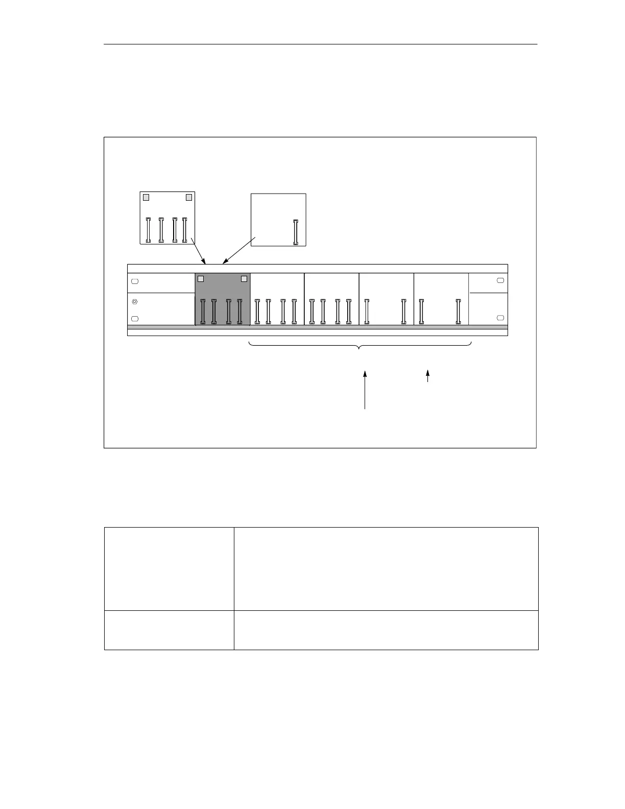
You can install up to 9 active bus modules depending on the length of the rail:
BM BM BM BM
A maximum of 8 BM 2 40 or BM 1 80
IM 153-x for ”module
change during operation”
For I/O modules
(SM/FM/CP) 80 mm wide
For 2 I/O modules 40 mm wide (SM/FM);
This requires a maximum of 4 bus modules
for an ET 200M
BM
IM/IM
BM
PS/IM
Redundancy with
2 IM 153-2
You can use the following bus modules depending on
functionality and installation setup:
BM
Figure 4-4 Installation setup with active bus modules
Placement of the PS 307 Power Supply Modules
Redundancy with
2 IM 153-2
Are you using the 530 mm rail?
Then you can install either 2 PS 307; 2A or 1 PS 307; 5A on the left
next to the BM IM/IM on the rail. (If you install the BM IM/IM in the right
latched position on the rail.)
Otherwise, you must install the power supply modules on a separate S7
DIN rail.
Recommendation: Each IM 153-2 should have its own PS.
IM 153-1/-2 for ”module
change during operation”
The PS 307; 2A fits next to the IM 153-x on the BM PS/IM.
The PS 307; 5A and 10 A don’t fit on the BM PS/IM. You must install
these on a separate S7 DIN rail.
Artisan Technology Group - Quality Instrumentation ... Guaranteed | (888) 88-SOURCE | www.artisantg.com

 Loading...


