Technical specifications
8.5 Hardware description
SIMATIC IPC647D
164 Operating Instructions, 01/2014, A5E32996306-AA
Displays and operator panel
8.5.4.1
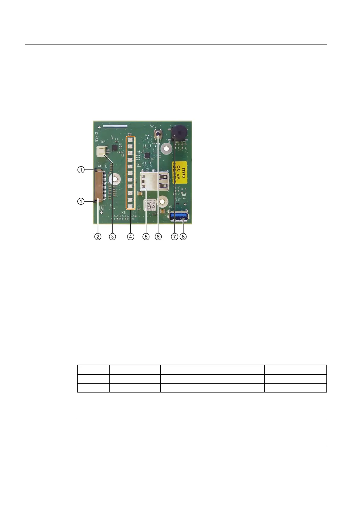
The operator panel is interconnected with the motherboard via a 26-pin flat cable. The flat
cable is plugged in at Position
② and secured by sliding the lock ① at the plug connector to
the right.
Plug connector, connection to the motherboard
Connection for external reset
USB socket, only the top USB contact is used
Pin assignment of the OP connectors
External Reset ⑦ type: JST B2B-PH-SM3-TB
External reset, (IO low max. 30 mA)
The device is reset when pins 1 and 2 (for example, by means of a pushbutton) are short-
circuited. It remains in this state until the short-circuit is cleared.
Note
Contact Customer Support or the Repair Center for detailed information on pin assignments
of the interfaces.