Technical specifications
8.5 Hardware description
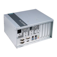
SIMATIC IPC847D
Operating Instructions, 01/2014, A5E32997454-AA
139
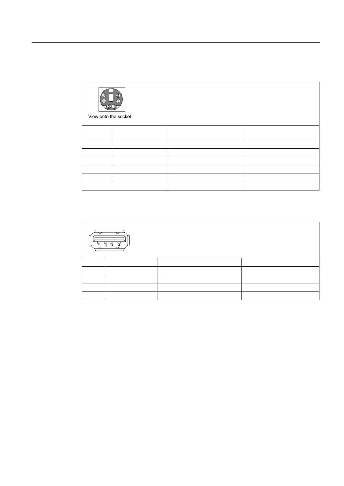
PS/2 keyboard interface, X21 1 to 6
Pin no. Short name Meaning Input
USB 2.0 ports, X4A, B; X561
The connectors are of type A.
The ports are rated as high-current USB 2.0 (500 mA).