Technical specifications
8.5 Hardware description
SIMATIC IPC847D
168 Operating Instructions, 01/2014, A5E32997454-AA
Displays and operator panel
8.5.4.1
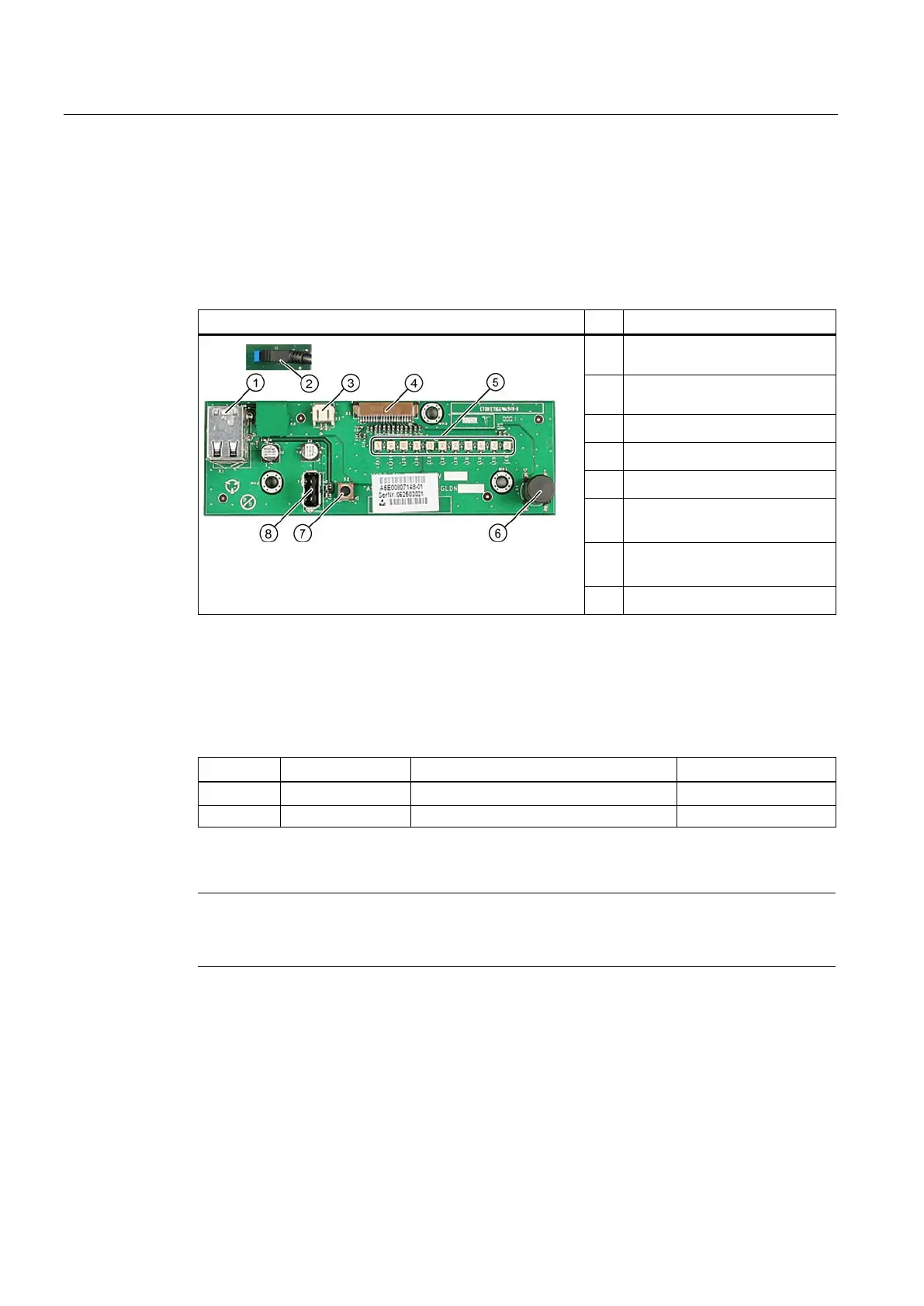
Operating panel - Layout and function
The operator panel is interconnected with the motherboard using a 26-pin connecting cable.
①
USB port: Only the top USB
②
20-pin pin header, on the rear:
Connection to the motherboard
External reset connector
Connection to the motherboard
LEDs
⑥
On/off button
Reset button
USB port
Pin assignment of the OP connectors
External Reset (3), type: JST B2B-PH-SM3-TB
External reset, (IO low max. 30 mA)
The device is reset when pins 1 and 2 (for example, by means of a pushbutton) are short-
circuited. It remains in this state until the short-circuit is cleared.
Note
Contact Customer Support or the Repair Center for detailed information on pin assignments
of the interfaces.