Configuring
S7-300 Programmable Controller Hardware and Installation
A5E00105492-01
4-9
4.5 Arranging modules on multiple module racks
Exceptions
CPUs 312 IFM, 312C and 313 can only be used for a single-rack module
assemblies!
Prerequisite: Interface modules
Interface modules (IM) connecting the S7-300 backplane bus to the next module
rack are required for assemblies on multiple module racks. The CPU is always
located on rack 0.
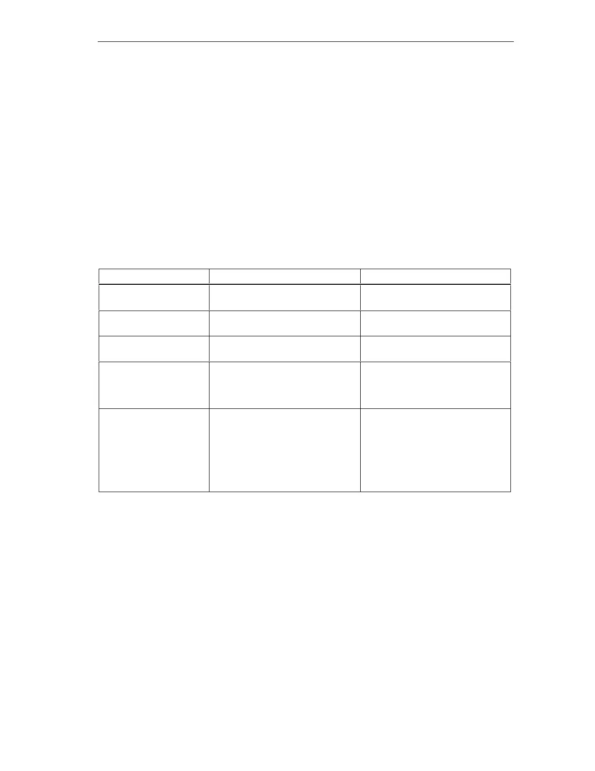
Table 4-4 Interface modules - Overview
Characteristics Dual- and multiple-line assembly Low-cost 2-line assembly
Send IM in module rack 0 IM 360
Order No.: 6ES7 360-3AA01-0AA0
IM 365
Order No.: 6ES7 365-0AB00-0AA0
Receive IM in module rack
1 to 3
IM 361
Order No.: 6ES7 361-3CA01-0AA0
IM 365 (hardwired to send IM 365)
Maximum number of
expansion devices
3 1
Length of the connecting
cables
1 m (6ES7 368-3BB01-0AA0)
2.5 m (6ES7 368-3BC51-0AA0)
5 m (6ES7 368-3BF01-0AA0)
10 m (6ES7 368-3CB01-0AA0)
1 m (hardwired)
Remarks - Module rack 1 can only receive
signal modules; total current load is
limited to 1.2 A, whereby the
maximum for module rack 1 is 0.8 A
These restrictions do not apply for
operation with interface modules
IM 360/IM 361
Rules: Arranging modules on multiple module racks
The following rules apply to the arrangement of modules on multiple racks:
• The interface module is always installed in slot 3, to the left of the first signal
module.
• No more than 8 modules (SM, FM, CP) are permitted per rack. These modules
are always located to the right side of the interface modules.
• The number of modules (SM, FM, CP) is limited by the permissible current load
on the S7-300 backplane bus. Total current consumption per line must not
exceed 1.2 A (see Technical data of modules).

 Loading...


