Configuring
S7-300 Programmable Controller Hardware and Installation
A5E00105492-01
4-15
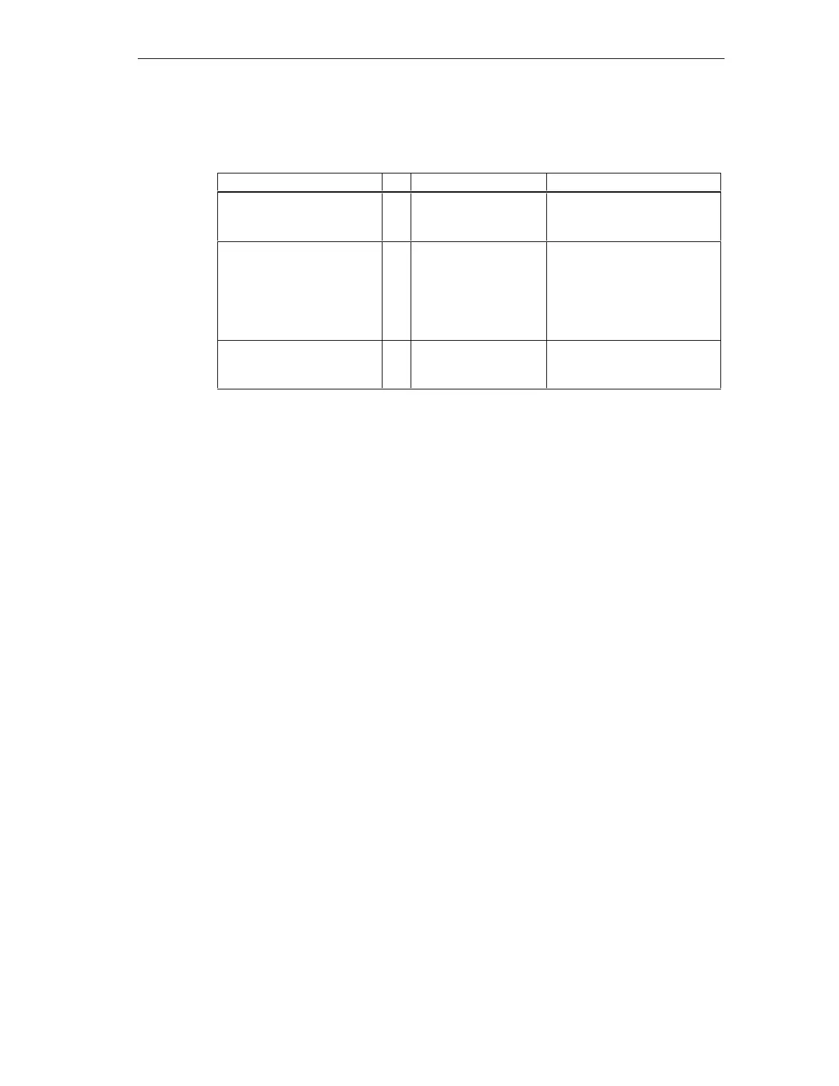
The table below shows components and protective measures.
Table 4-7 VDE specifications for the installation of a PLC system
Compare ... 1) VDE 0100 VDE 0113
Disconnecting devices for
control systems, sensors
and actuators
(1)
... Part 460:
Master switch
... Part 1:
Circuit breaker
Short-circuit/overload
protection:
In groups for sensors and
actuators
(2) ... Part 725:
Single-pole fusing of
circuits
... Part 1:
• In the case of a grounded
secondary circuit: Provide
single-pole protection
• Otherwise: Provide all-
pole protection
Load power supply for AC
load circuits with more than
five electromagnetic devices
(3) Galvanic isolation by
transformer
recommended
Galvanic isolation by
transformer mandatory
1) This column refers to the indexes of the figure in the Chapter Overview: Grounding.
Further information on protective measures ...
e.g. EMC/lightning protection is found in the Appendix.
4.8.2 S7-300 installation with grounded reference potential
Introduction
In an S7-300 configuration with grounded reference potential occurring interference
current is dissipated to the ground conductor/ to ground. A configuration with
grounded reference potential is possible with following CPUs:
• CPU 312 IFM and CPUs 31xC
(internally hardwired)
• CPU 313, 314, 314 IFM, 315, 315-2 DP, 316-2 DP, 318-2 DP
(bridged terminals M and functional ground)
Connection block diagram
The figure below shows an S7-300 assembly with CPU 313, 314, 314 IFM, 315,
315-2 DP, 316-2 DP, 318-2 DP and grounded reference potential. If you want to
ground reference potential, you must not remove the bridge on the CPU between
the M terminal and functional ground.

 Loading...


