Analog modules
6.7 Analog input module SM 331; AI 8 x 12 Bit;(6ES7331-7KF02-0AB0)
S7-300 Automation System Module data
Manual, 08/2006, A5E00105505-04
6-49
Hardware interrupts
You can set the hardware interrupts of channel groups 0 and 1 in
STEP 7
. However, always
set a hardware interrupt only for the first channel of a channel group, i.e. either at channel 0,
or at channel 2
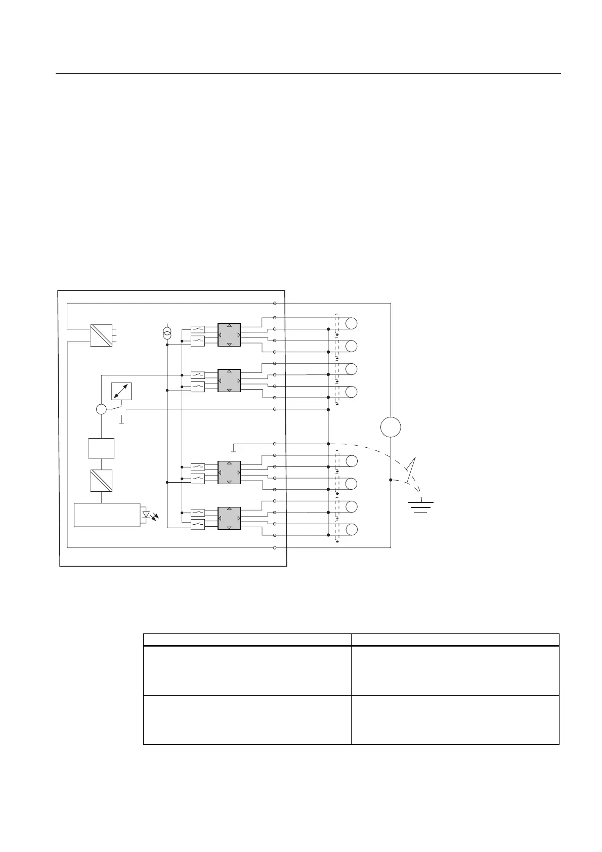
Terminal assignment
The following diagrams show different possible forms of wiring. The input impedance is
determined by the measuring range module setting, see table
Measuring methods and
ranges
.
Wiring: Voltage measurement
9
9
9
9
9
9
9
7
6)
&+
&+
&+
&+
&+
&+
&+
&+
&RPS
'&
9
9
/
0
0
ದ
0
ದ
0
0
0
ದ
0
$1$
0
0
0
ದ
0
ದ
0
0
0
ದ
0
ದ
0
0
0
)XQNWLRQV
HUGH
5¾FNZDQGEXV
$QVFKDOWXQJ
3RWHQ]LDO
WUHQQXQJ
LQWHUQH
9HUVRUJXQJ
6WURP
TXHOOH
LQW
.RPS
NHLQH
0XOWL
SOH[HU
0HVVEHUHLFKV
PRGXOH
$'8
H[W.RPSHQVDWLRQ
3RWHQ]LDO
DXVJOHLFK
Figure 6-14 Block diagram and wiring diagram
Measuring range module settings
Measuring range Measuring range module setting
± 80 mV
± 250 mV
± 500 mV
± 1000 mV
A
± 2.5 V
± 5 V
1 V to 5 V
± 10 V
B

 Loading...


