Analog modules
6.7 Analog input module SM 331; AI 8 x 12 Bit;(6ES7331-7KF02-0AB0)
S7-300 Automation System Module data
6-50 Manual, 08/2006, A5E00105505-04
Wiring: 2 and 4-wire measuring transducer for current measurement
9
7
6)
&+
&+
&+
&+
&+
&+
&+
&+
'&
/
/
0
0ದ
0ದ
0
0
0ದ
0$1$
0ದ
0
0
0ದ
0ದ
0
0
0ದ
&203
0ದ
0
0
0
0
0
0
/
/
/
)XQFWLRQDO
JURXQG
%DFNSODQHEXV
FRQQHFWLRQ
(OHFWULFDO
LVRODWLRQ
,QWHUQDO
VXSSO\
&XUUHQW
VRXUFH
LQW
FRPS
1RQH
0XOWL
SOH[HU
0HDVXULQJ
UDQJHPRGXOHV
$'&
H[WFRPSHQVDWLRQ
(TXLSRWHQWLDO
ERQGLQJ
'08
'08
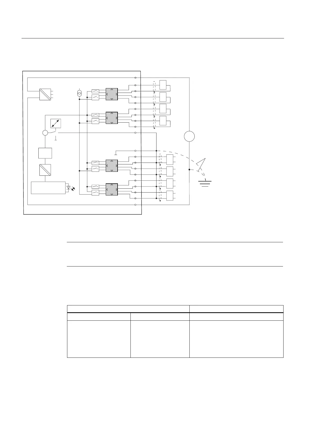
Figure 6-15 Block diagram and wiring diagram
Note
The connection between M
ANA
and M- (terminals 11, 13, 15, 17, 19) is not needed for
grounded 4-wire transducers with a non-electrically isolated supply.
Measuring range module settings
Measuring range Measuring range module setting
2-wire transducer 4 mA to 20 mA D
4-wire transducer ± 3.2 mA
± 10 mA
0 mA to 20 mA
4 mA to 20 mA
± 20 mA
C

 Loading...


