Digital modules
3.24 Digital output module SM 322; DO 16 x DC 24 V/0.5 A: (6ES7322-8BH10-0AB0)
S7-300 Module data
Manual, 06/2017, A5E00105505-AJ
149
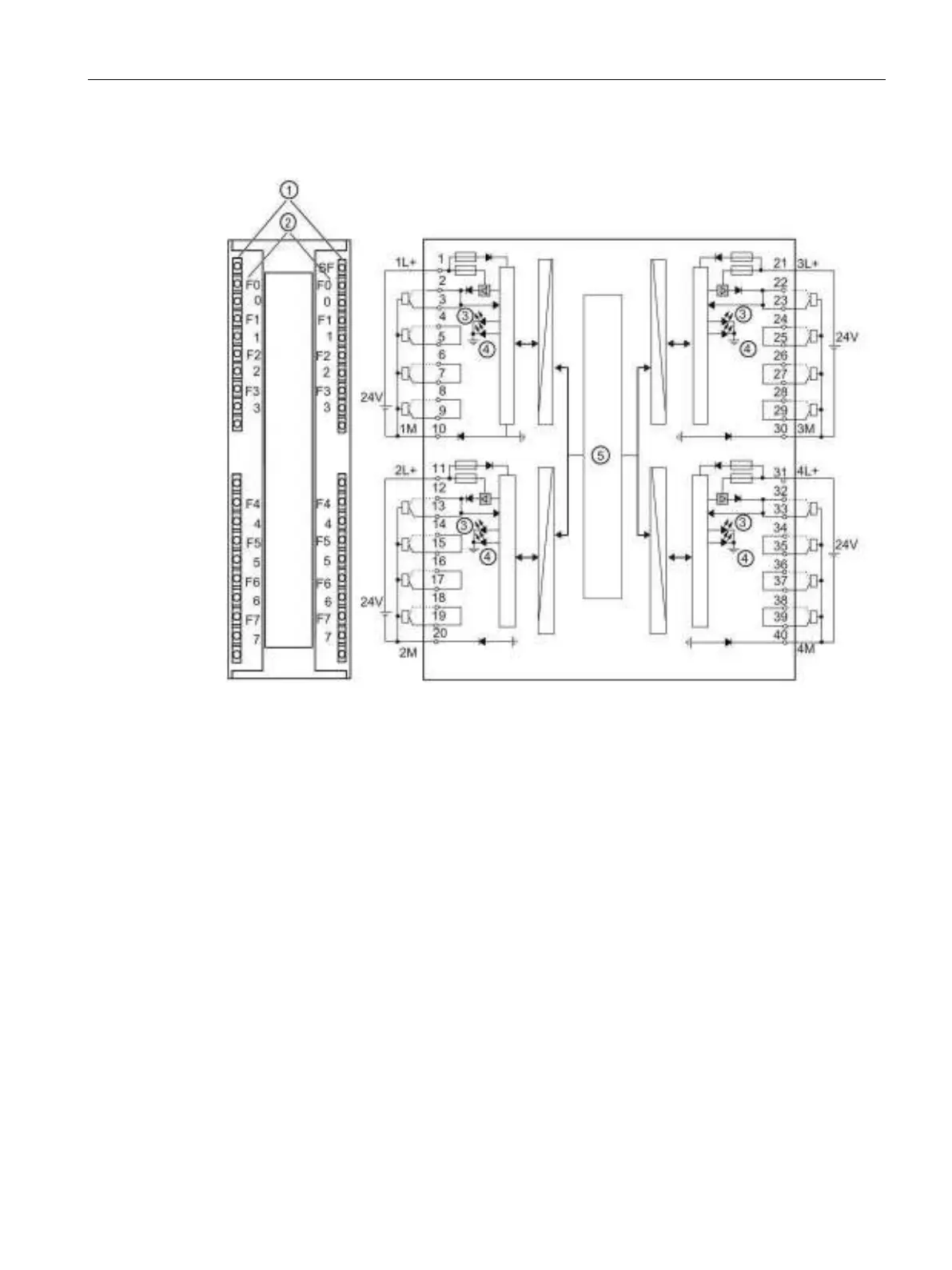
Wiring and block diagram
Status displays - green
Channel numbers
Numbers 0 to 7 on the right side correspond to channel numbers 8 to 15
Redundant Output Signals
Two clamps are on each channel. Both connections are similar and can be used for a
redundant control of an actuator. Redundant control can take place from 2 different modules
without an external circuit. Both signal modules must be connected to the common reference
potential M.