Parameter sets of signal modules
A.6 Parameters of analog input modules
S7-300 Module data
536 Manual, 06/2017, A5E00105505-AJ
Note
The representation of limits matches the analog value representation (see chapter 4.)
Observe range limits when setting the limit values.
Interference frequency suppression
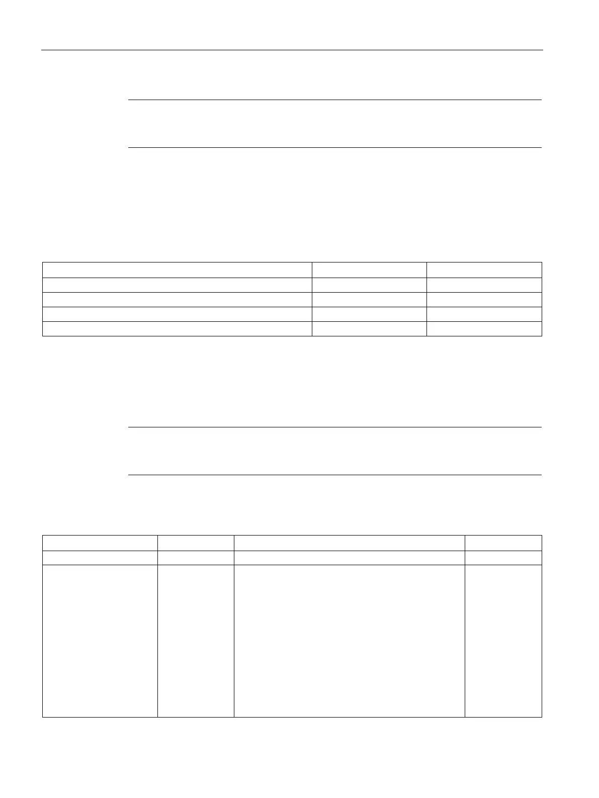
The table below contains the coding at byte 1 of data record 1 for the various frequencies
(see the previous figure.) Make allowances for the resultant integration time at each channel!
Table A- 7 Interference frequency suppression codes of analog input modules
Interference frequency suppression
Measurement types and measuring ranges
The table below shows all measurement types and measuring ranges of the analog input
module, including their codes. Enter these codes at bytes 2 to 5 in data record 1 (refer to the
previous figure.)
Note
You may have to reposition a measuring range module of the analog input module to suit the
measuring range.
Table A- 8 Measuring range codes of analog input modules
Voltage 2#0001 ± 80 mV
± 250 mV
± 500 mV
± 1 V
± 2.5 V
± 5 V
1 V to 5 V
0 V to 10 V
± 10 V
± 25 mV
2#0001
2#0010
2#0011
2#0100
2#0101
2#0110
2#0111
2#1000
2#1001
2#1010