• Thin sheets (shims) can be placed under the motor mounting feet to align the motor and to
avoid mechanically stressing the motor. The number of shims used should be kept to a
minimum.
• In order to securely mount the motors and reliably and safely transfer the drive torque, bolts
with strength class 8.8 according to ISO 898-1 should be used.
Note
Comply with permissible vibration values
All ange-mounted motors must have a stable motor suspension assembly and for high eld
weakening speeds must be supported using the appropriate feet at the bearing end shield
(foot/ange type of construction, also refer to Section "Vibration severity limit values").
Support using feet at the bearing end shield is not required if the following conditions are
maintained:
- For ange-mounted motors, there is a stable motor suspension design
- The permissible vibration values according to DIN ISO 10816 are maintained
- The maximum speed is limited (refer to Table "Restricting the maximum speed")
Motors that are mounted, as a result of their type of construction, to the wall using the motor
feet, must be xed in place using an adequately dimensioned positive form t (e.g. using
studs or mounting rails).
When commissioning the motors, it must be ensured that the permissible vibration values
according to DIN ISO 10816 are maintained.
Table 4-31 Limiting the maximum speed
Shaft height
mm
Max. permissible speed
r/min
180 3000
225 2500
280 2000
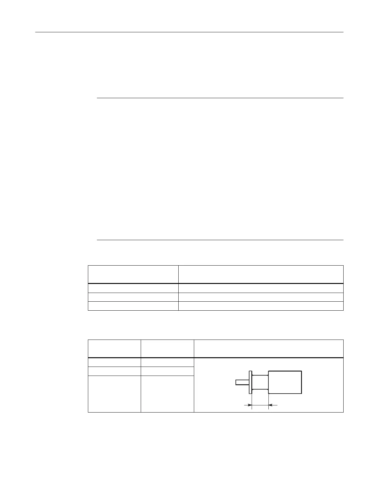
Table 4-32 Flange mounting with threaded studs and nuts
Shaft height
mm
M1
mm
180 32
225 45
280 45
Mechanical properties
4.10Vibration response
1PH8 SIMOTICS M main motors
Conguration Manual, 12/2022, A5E51895839A 147