0RWRUSRZHU
6SHHG
Q
1
Q
PD[,QY
3
PD[
3
3
1
6
Q
PD[
Q
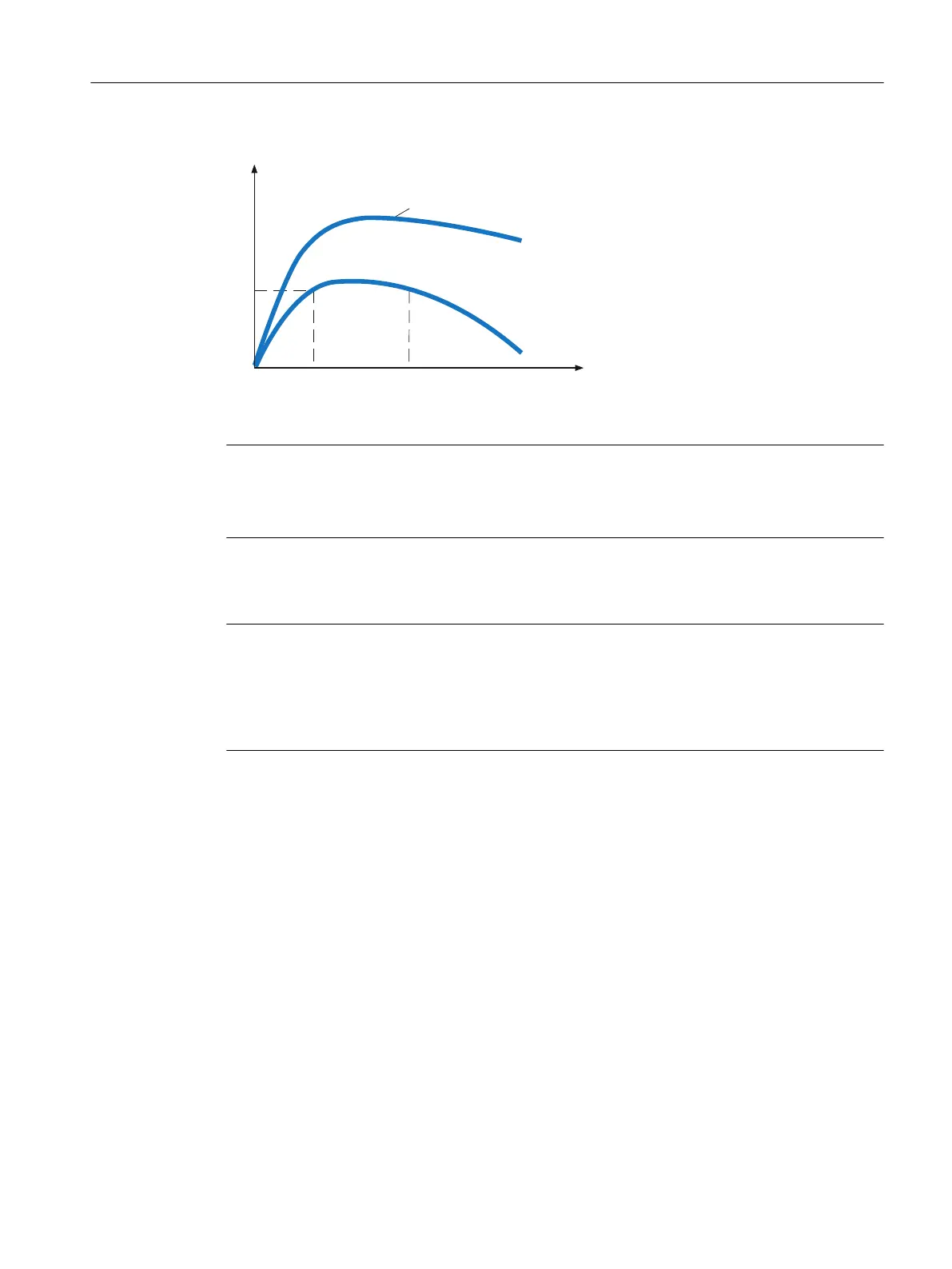
Figure6-5 Typical speed/power diagram for 1PH8 three-phase synchronous motors
Note
Like those for induction motors, the data sheets for the supply voltage "ALM400V" include
additional ancillary rated points for the conguring of main spindle applications for machine
tools. These allow an extended speed range to be congured.
The theoretical curve of the maximum permissible overload capacity is shown as a limit in
the characteristic diagrams and corresponds to value P
max
.
Note
Voltage limitation
A SINAMICS Voltage Protection Module (VPM) is required for operation at speeds of n
max,Inv
and
above. Voltage Protection Modules are available for rated currents up to 200A.
For further information, please refer to the SINAMICS S120 conguration manuals.
6.2.5 Selecting synchronous-reluctance motors
Characteristics for synchronous-reluctance motors
For synchronous-reluctance motors, the S1 characteristic (uninterrupted duty) has a response
similar to that for synchronous motors. The S1 characteristic represents the thermally maximum
possible continuous torque that can be produced.
As a result of the very low rotor losses, in the medium speed range, synchronous-reluctance
motors have a higher thermal utilization and when compared to induction motors, have a
better eciency class. When conguring, one of two versions can be selected:
• Eciency (IE3 to IE5)
• Performance (IE2 to IE4)
Conguration
6.2Procedure when engineering
1PH8 SIMOTICS M main motors
Conguration Manual, 12/2022, A5E51895839A 211

 Loading...


