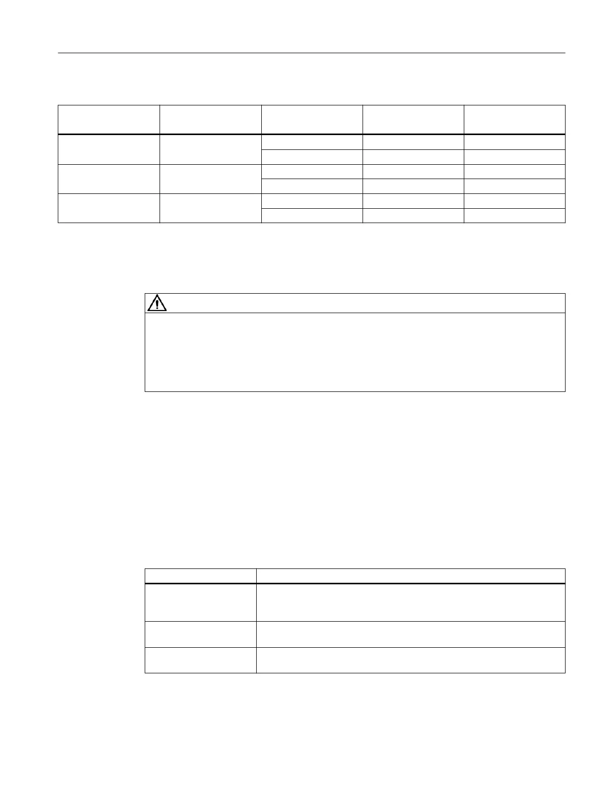
Table 4-6 Diameter, minimum air ow and pressure drop
Shaft height
mm
Diameter
mm
Degree of protection Minimum air quantity
m
3
/s
Pressure drop
Pa
180 300 IP23 0.21 450
IP55 0.17 550
225 350 IP23 0.33 600
IP55 0.31 650
280 Adapter required IP23 0.52 600
IP55 0.42 600
4.1.3 Water cooling
WARNING
Defective work on the cooling circuit
Defective work on the cooling circuit can cause injury and/or damage to property.
• Only qualied personnel may assemble, install, and commission the cooling circuit.
• Perform installation or service work on the cooling circuit only when the system is de-
energized.
The electrochemical processes that take place in a cooling system must be minimized by
choosing the right materials. For this reason, mixed installations, i.e. a combination of dierent
materials, such as copper, brass, iron, or halogenated plastic (PVC hoses and seals), should not
be used or should be limited to the absolutely essential minimum.
There are 3 types of cooling circuits:
• Closed cooling circuit
• Semi-open cooling circuit
• Open cooling circuit
Table 4-7 Description of the various cooling circuits
Denition Description
Closed cooling circuit The pressure equalizing vessel is closed (oxygen cannot enter the system)
and has a pressure relief valve. The coolant is only routed in the motors and
converters as well as the components required to dissipate heat.
Semi-open cooling circuit Oxygen can only enter the cooling system through the pressure equalization
vessel, otherwise the same as "closed cooling circuit."
Open cooling circuit (tow‐
er system)
The coolant is cooled in a tower. In this case, there is intensive oxygen con‐
tact.
Mechanical properties
4.1Cooling
1PH8 SIMOTICS M main motors
Conguration Manual, 12/2022, A5E51895839A 71